Willie digitalisiert

In den 1980er Jahren kamen in Japan die musikalischen Porzellanfiguren der Firma Melody-In-Motion(tm) auf den Markt. Die Wiedergabe der Musik erfolgte von einem Endlos-Tonband, welches vom selben Motor bewegt wurde wie auch die mechanischen Funktionen der Figuren.

Beim hier gezeigten Clockpost Willie (“Pennerwillie an der Uhr”) dreht sich der Kopf der Porzellanfigur hin und her. Neben der Abnutzung des Bande kommt es durch Ermüdung von Kunststoffteilen nach den nunmehr etlichen Jahren seit der Herstellung häufig zu “Bandsalat”, die Reparatur der Mechanik erschien mir nicht sinnvoll. Bisher als Ersatz erhältliche “Digital-Chips” sind aktuell nicht verfügbar, so dass die hier vorgestellte Ersatzplatine entstand.

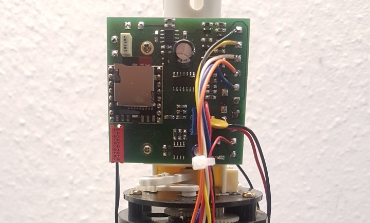
Die Platine setzt ein Standard-MP3-Playermodul ein und ergänzt die Ablaufsteuerung (uhrgesteuert oder Dauerbetrieb), den Leistungsverstärker, die Stromversorgungsschaltungen und die Drehzahlsteuerung für den Motor, der nunmehr nur für die Bewegung der Figur verbleibt.

Die Batteriespannung wird überwacht und bei niedriger Spannung abgeschaltet; eine Ausgabe eines als MP3-Daten vorliegenden Hinweistones, die Absenkung der Lautstärke oder eine andere Art der Signalisierung ist denkbar, aber aktuell nicht umgesetzt.

Zum Abschluss ein kurzes Video des fertigen “Willie”, leider hat die Handy-Kamera den Ton etwas verzerrt.

First impressions

As this is a techie blog, I’ll start with some impressions of the electronics as I found them when I disassembled the Ondes Martenot.
I assume some knowledge about the function of this instrument. If you’re new to the Ondes Martenot, you’d probably like to have a look at Thomas Blochs website and Wikipedia

This is the main electronics unit from below.
Almost all film capacitors (most of them of the paper type, sealed with tar in a glass tube) and resistors need to be replaced either of degradation in value, short or open circuit.

On the left side, within two separately shielded boxes, are the two LC oscillators, each featuring an EF94 (6AU6) pentode tube. As you may already now, the Ondes Martenot is based on beat-frequency oscillators, like the Thermin or the Spärophon. The fixed (more or less at least – it is tunable to achive tuning of the instrument) oscillator is told to oscillate at 200kHz – I still have to verify this, but for now, let’s assume it is correct. An additional transpose switch also works on the fixed oscillator.
The second one is set up to be variable between 180 and 200kHz by means of either a keyboard or the ribbon controller with the finger ring typical to the Ondes Martenot. While the ribbon controller works on a gigantic variable capacitor (the conductive ribbon passes an array of capacitor plates, photos will follow), the keyboard switches a string of inductors. This gives the higher note priority known from many other monophonic synthesizers. In addition to the keyboard or ribbon control, two push buttons with switchable capacitors and 3 metal knobs also connected to the LC tank circuit via low value capacitors allow for further influence on the tone. Switch No. 7 adds some lose coupling from the variable oscillator output to the grid circuit, its function will be further analyzed when the mixer circuit is operational as it also changes the mixer configuration.

The third EF94 tube is used as a mixer, bringing back the outputs of the two oscillators into the audible range between 0 and 20kHz.  The mixer is followed by the fourth EF94 as a pre-amplifier. Its screen grid is connected to some circuitry in the drawer (see below) to allow for various sound modification.

Final amplification is accomplisged by an EL84 output pentode. Volume control, which is major important for the Ondes Martenot because of its free wheeling oscillators, is achieved with the “touche d’expression”, a large button on the drawer with compresses a little bag with conductive powder. Working like a carbon powder microphone, it emulates a potentiometer in the EL84’s cathode circuit. The output transformer is somewhat special because of its three secondary windings for three different speakers which could be operated simultaneously on the Ondes Martenot. Two filter functions are realized within the output amplifier: Switch No. 0 allows to connect a choke in series with the output transfomer’s primary winding, and a capacitor in series with a potentiometer connected in parallel with the primary allows for tone control. This potentiometer is also of the carbon bag type, operated by a knee pedal.
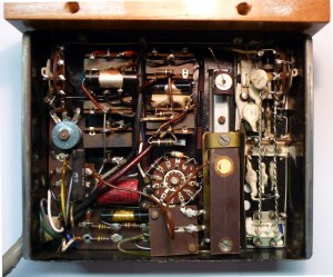
This photo shows the inside of the drawer. This small panel contains almost all important controls of the Ondes Martenot.
On the right side you can see the switch toggling between keyboard and ribbon control (upper right corner) and the push buttons and metal knobs influencing the variable oscillator mentioned above.
The big rotary switch in the lower center allows for logarithmic control of the output level for the main speaker (D1, “diffuseur principal”) to match its volume with other speakers. Nine toggle switches allow for various sound modifications, while the switch in the upper left corner connects a bridge rectifier (the blue disky thing on the left) in series with the output.

One can assume that all those modifiers enable interesting effects on the originally generated sine wave. The next step towards the synthesizer would probably be a sawtooth oscillator like the Trautonium used.
340A vs Wavecomputer 360A

Someone may ask why one should get a bulky 19″ rack when it is just a re-packaged Wavecomputer 360A.
Of course it is much more than that, although the 340/380 case still contains lots of nothing…

First of all, the 340/380 has the additional 380, the sequencer unit. But the topic of this post are the differences between a Wavecomputer 360A and the 340A/340B combo.
All waves on the Wavecomputer 360A are made up of a fixed set of 64 so called “partial waves” of 128 wave samples each stored in ROM, being unalterable for the user. This is more than enough to have lots of fun, as Kenneth shows us on his website – but for those who even want more fun, the 340 offers flexible partial waves because of its RAM storage. In the original models, the partial waves can (and actually must) be loaded from mini cassette, while this modified model allows for up- and downloading of wave data from and to a PPG Waveterm. At this moment, we can only guess about what would be possible with Armin Stöwe’s Wavecutter Software!

But there’s another thing about the partial waves I can say for sure today. When I wrote that the Wavecomputer 360A had 64 partial waves of 128 samples each, I sugarcoated the machine a bit. As everybody in the 1970s, also Wolfgang had to household with memory space. So he decided to store only half waves of 64 samples each in ROM and calculate the second half by reflecting all wave samples through the origin. This is a simple yet genial thing in digital electronics – he just inverted the wave sample address lines together with the data lines of the wave memory. This is the first step of building the 2’s complement of a binary number, which is the negative representation of the number for most arithmetical operations – and sufficient for the intended task.

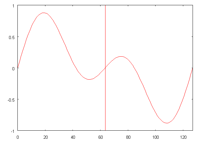
This is a fictional partial wave on the Wavecomputer 360A. The second half (after the vertical red line) is exactly symmetrical to the left half with respect to the origin.
Mathematically said, it fulfills f(x) = -f(-x)  –  the minus before the x is the inversion of the address lines, the minus of the function expression the inversion of the data lines.

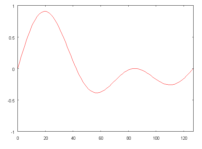
With the PPG 340, this is not necessary anymore.  The TONR module which holds the active partial waves now has 8kBytes of memory, so that the 64 partial waves can be stored completely with 128 wave samples each.
The inverters have been omitted and partial waves like the one below are now possible.

340/380 Common Talk

First, some facts on what this is all about.

PPG’s 340/380 is a wavetable based synthesizer with highly customizable partial waves, 8 voices and a built-in sequencer. It consists of three 19″ boxes, each of them being 3 units high, connected with a 50 wire bus cable.

The PPG 340A, called Generator Unit,  contains the Waveomputer 360A’s main board, fitted with four generator boards making up a total of 8 independent voices together with a modified TONR (wave memory) board and the former IO board less the 6802 processor and many other parts.

The PPG 340B is the Processor Unit, containing a new processor board called PER, featuring a 6802 CPU, some RAM, an UART connecting a serial terminal to the 340B, a timer chip, some I/O and circuitry to operate a mini cassette drive. Furthermore, 32kBytes of RAM and 4kBytes of ROM are installed in the 340B. The ROMs originally hold the boot loader allowing to boot the system from mini cassettes.

The third unit is the PPG 380 Event Generator, a highly programmable sequencer. Equipped with the same CPU, ROM and RAM boards as the 340B but with slightly more (48kBytes) RAM it was also booting its actual intelligence from mini cassette. A dual port RAM board interfaces the Event Generator to the mentioned 50 wire bus allowing for high speed messaging from the sequencer unit to the Wavecomputer.

This machine is different from the factory version in so far as Armin Stöwe has promoted it to talk PPG Bus. This way the 340B and 380 are fed with machine code and wave data via the Waveterm, samples can be edited, saved to and loaded from the Waveterm and maybe much, much more… Too sad that we can’t ask Armin about that anymore.