Restoration of EMT 250s

The model 250 digital reverberator from EMT is quite special. First of all, it looks like the oil radiator from Uhura’s boudoir. In germany the EMT 250 is usually called <Weltraumheizung> (space radiator) because of that.

As the developers of the digital circuit, Dynatron, feared that their design could be copied they removed all markings from the ICs – and there are many – of the logic board. Only the RAMs and some static shift registers used for pre-delay are usually untouched.

The main logic board is completely wire-wrapped, something not seen that often outside of vintage industrial control, aircraft and military equipment.

(Images an some info on the first 250 I worked on will follow…)

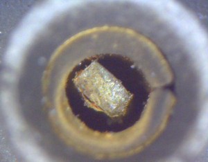
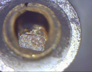
The second 250 was hit much harder. Some kind of heavy corrosion destroyed about two dozens of ICs. Their pins look rusty and broke off partially while trying to pull the ICs from their sockets. All of them seem to be from one manufacturer, other ICs with a different looking body do not show any traces of corrosion.

Further investigation with a microscope immediately after removing an IC revealed that some pins were already broken some time before the attempt to pull the IC:

The next task is now to remove the remainings of the pins, clean the sockets and re-populate the board with ICs.

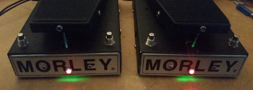
New hope for Morley

As green is said to be the color of hope, those two oldies should now have lots of it.

They came to me with the classic light bulb, one missing the photo resistor, and both featuring a nice 115VAC transformer and a power cord good for an average home.
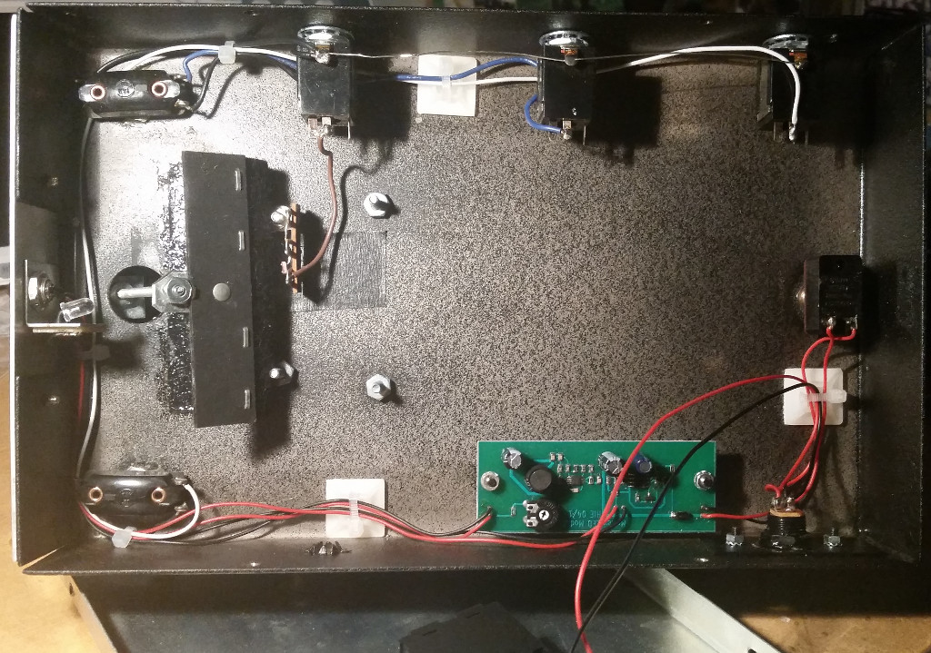
The task was to identify a suitable photo resistor (bad, bad CdS stuff that the EU does not want us to use anymore. Maybe they think all the cadmium is urgently needed for cheap chinese power tools that find an early end in the dustbin due to their quality anyway?), remove the circuitry and design a driver circuit for a LED – a green one, matching with the sensitivity maximum of the photo resistor. A switch mode converter was used to allow the longest possible operation from 9 volts battery. For this purpose, a battery compartment has been mounted into the base plate. As soon as the battery voltage drops below 7.5 volts, the red indicator LED on the front starts flashing slowly.

Here’s the new circuitry:

AKG ADR68k

An ADR68k showed up with multiple problems and a common symptom: no function, except from the remote telling it cannot find the main unit. The first obvious fault were broken ZIF sockets and an EPROM travelling the 19″ case. Replacing the sockets did not help much, as the power supply was starting to develop a high current smell.
The crowbar circuit tried to force down the linear +5V regulator which is good for up to 10 amps, causing the SCR to get very hot until it finally shorted out. The regulator uses a sense circuit with the power and regulator ground being seperately connected to the main board via a connector – this one:

I know those connectors in a similar or worse condition quite well from pinball games. In this case the resistance of the power return has increased, the regulator tried to compensate and finally lost against the crow bar.

A careful rework of the PSU, including replacement of previously installed cheap capacitors, soldering the wires directly to the main board brought the unit back into operation.

But there still was a input level indication without any signal. It turned out that the PCM53-I DAC in the ADC circuit had an offset on the output and needed to be replaced.


Lexicon PCM42

What we’ve got here is a Lexicon PCM42 delay unit which some techs have already been working on.
While the inital problem was some kind of distortion, the delay path was pretty messed up when it came to me. Well below the yellow LED of the input level indicator was lit the input signal to the A/D converter was heavily clipped.

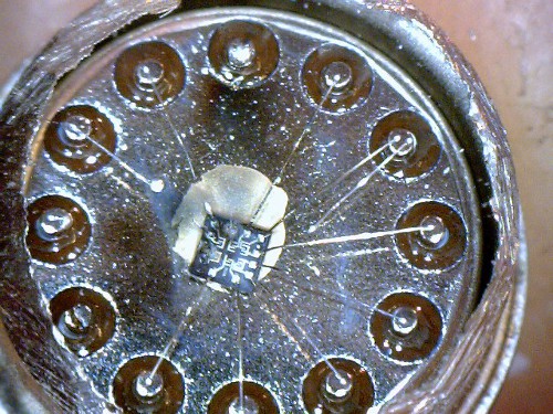
It became clear very soon that the unit uses some kind of compression/expansion technique to virtually increase the A/D and D/A resolution, similiar to A-law or µ-law used in telephony as well as by other music applications realized by simple non-linear amplifiers built around a RCA CA3039 diode array. Some measurements made sure that those diodes were actually not where they’re supposed to be. I did not care whether a defective (how should that be – the array is connected via rather high resistors to the circuit preventing excessive current flow) or fake CA3039 was causing this but ground the thing open:

What we see here is obviously not a fake, but a very dead CA3039. One single diode junction has survived, and judging from the vaporized bond wires, the current must have been rather high – much higher the circuit ever allows.

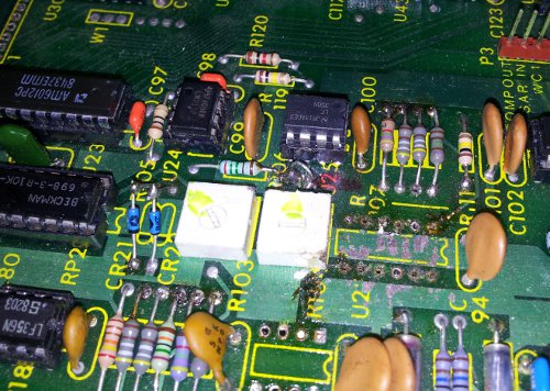
On further examination I found serveral component leads being clipped and soldered back together, maybe to measure those parts out of circuit.  Some copper tracks have unfortunately been damaged too.

A rather important 2.55kOhms resistor has not been reconstructed so I decided to restore the unit before doing the actual trouble shooting. After the resistors, capacitors, two diodes, the CA3039 and a LF356 that has previously been identified to be defective had been replaced.

A first test probably showed the initial problem with the PCM: the delayed output was clipping on one half wave at any input level.
Some signal tracing revealed that very first op amp followng the Am6012 DAC in the reconstruction (read: D/A) path showed a 0.6 volts DC offset on the output, way too much to be compensated by the offset trimpot.
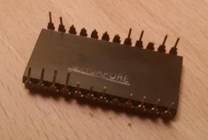
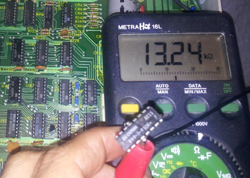
Now there were not many parts left to be checked: the Am6012 DAC chip, the output resistors and the op amp itself. The latter one was easily ruled out by swapping, and as I did not have a AM6012 handy, I checked the resistors. Et voila: each of the two DAC outputs is pulled to an internal +10V reference by two paralleled 10k resistors, being part of a 8x10k DIP array. While 7 of the resistors were well within tolerance, one measured this:

This is more than enough for the measured offset voltage. After replacing the resistor pack by 8 precision resistors the delayed output was clean, symmetrical and free from clipping.
Once again cleaning up after some other’s repair attempts was much more costly than the repair itself. But the most important thing is that a great piece of studio equipment is alive again!

Kleine Hummel

Recently this nice amplifier from Klein + Hummel found its way to me.
I have no idea when I will find some time to clean and fix it, but this should no mean to keep some photos from those who are interested in interesting gear:

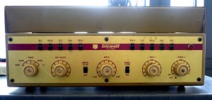
Klein + Hummel Telewatt Ultra front view

Front view with top cover. The Telewatt ultra was also available in a build-in version without the cover.


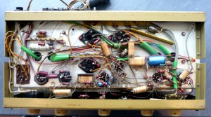
Klein + Hummel Telewatt bottom view

The internals: first the legendary metal-paper capacitors will be checked and probably replaced, same for the electrolytics.


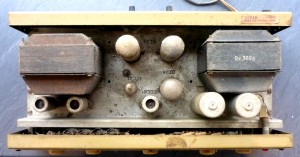
Klein + Hummel Telewatt Ultra top view

Top view. Yes, it does need some cleaning. Once cleaned, two EL34s will show up delivering 40 watts RMS into the speaker.
I’m quite curious how this little beast will sound…


Creamware A16 DC modification

Honestly – serious production with Midi-to-CV to control analog synthesizers seems to be impossible. 7 bits translates to quite large steps in the control voltage. But how about using an studio grade 18 bit A/D – D/A box driven via ADAT?
If a Creamware A16 comes into your mind, you’d better think twice about it. There are some reasons converters like this are hard to modify for precise DC:

  • First of all, the inputs are capacitively coupled. But of course it can’t be as easy as just bypassing the caps…
  • Both the ADCs (Philips SAA7367) and the DACs (Philips TDA1305) use single +5V supply. This implies that the analog signals need to be centered around an internally generated reference voltage
  • The reference voltages are not quite precise. Although their long-time stability is very good, the initial accuracy is 5% or worse. Therefore also the signal range varies from chip to chip.
  • The ADCs have an integrated high pass filter to remove DC offsets, but fortunately it can be easily disabled by lifting up one pin and strap it to ground

The engineers saved some parts by not subtracting the DAC refence voltage from the outputs, but lifted the ground potential of all 32 jacks by the reference of the first DAC (channels 1 & 2). For this purpose, a high power voltage follower with massive decoupling on the output was designed. As the reference voltages differ from DAC to DAC, this approach would not work for DC, so I removed the circuitry and connected the jack ground to circuit ground.

When I was working on the PSU – a quite strange design by the way – I modified two regulators to supply +/-7.5 volts to the op amps because in the original design the op amp supplies were a) somewhat too low and b) shifted by the same amount the jack grounds are lifted beyond ground.

A last modification to the PSU applies to precision and stability: the analog supply which influences the reference voltages was derived from a LM317’s output by means of a voltage divider and a power voltage follower – including thermal drift. To improve the absolute precision of the converters, I replaced the resistive voltage divider with a TL431 shunt regulator.

But things became even worse…

While doing some measuring with the ADAT in and out jacks connected I found that the outputs are inverted with respect to the input voltage. With an ADAT box and appropriate software I was able to determine that the inversion takes place between ADAT-In and the analog output of the DACs, so another inversion in necessary here, including subtraction of the reference voltage.

This was accomplished by inverting the reference output of each DAC chip (there’s one reference per chip), but due to the rather high impedance of the reference pin, a voltage follower was necessary too. The inverted reference and the DAC output voltage are then summed up with an op amp. This op amp drives the output jack’s tip connection via 300R for protection and EMI purposes, while the feedback to the adder is connected after the protection resistor so that the input impedance of the connected load does not influence the output voltage up to a certain grade.

Both the reference and the DAC output are summed up via a series connection of a fixed and a variable resistor to allow to compensate the differences between the DAC chips.

By cutting several traces and soldering some components to the IC pins, not to mention the tons of RTV used to mount the variable resistors, it was possible to build both adders, the voltage follower and the inverter stage around the op amps previously used to drive the outputs.

Really…?
Actually – not. Originally NE5532’s were used, but as I needed  to add another 8 op amps (read on to learn why), the current draw would probably have blown the PSU some day. The whole 1.3 amps were already fed through one single LM337, so I decided to remove all 5532’s (offset voltage: 0.5mV typ) and replace them by MC33078’s, which offer an improved offset of 0.15mV typ. at less than half the power consumption.

A similar treatment applies to the input channels. In the original circuit, the positive input (on the ring of the phone jack!) is capacitively coupled and mixed together with the inverted tip signal using the input op amp of the SAA7367 ADC as summing amplifier. For the DC modification it is required to add the DC input signal and the reference voltage, which is generated individually for each ADC input, and feed the result without inversion to the ADC.

Unfortunately this requires two op amps per channel – but there is only one NE5532 for two channels. Besides replacing the 5532 with the above mentioned MC33078 I piggy-packed another 33078 which inverts the inverted sums for two channels.

Obviously this is only possible with some additional wiring and rather bohemian component placement.
Not to mention another ton of RTV to keep the potentiometers in place – one for the input gain and one for the offset voltage, as for the DAC channels.

After all this makes 24 ICs and about 250 resistors to be removed and then about 200 new resistors, 16 capacitors, 32 ICs and 64 (as in six-ty-four) multi-turn potentiometers to be installed, not to mention the modifications on the PSU board.

After initial calibration, the zero offset of the DACs was kept within 1mV over several days. The gain was calibrated so that 5.0 volts input results in a reading of -1dBFS. This was recorded as a reference signal and used to adjust all output channels to 5.000 volts.

Stay tuned for some more photos…

Quad Eight RV-10

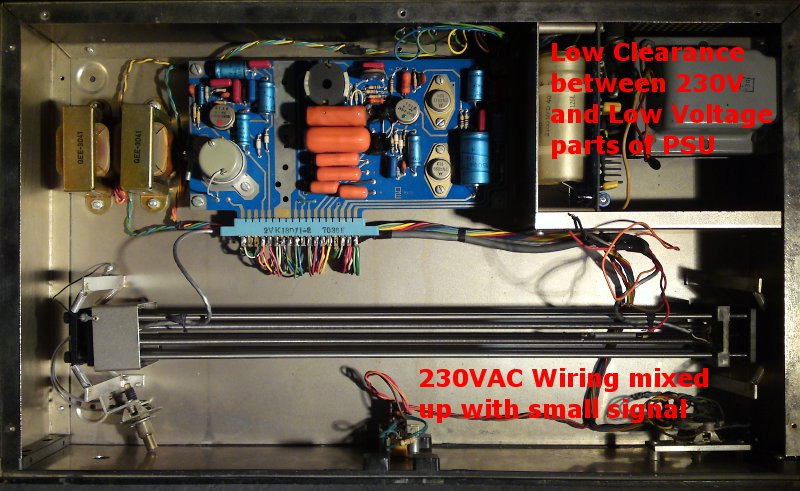
Slightly more than the intended re-cap rehab – this 40 years old spring reverb does not only get new electrolytics to replace the leaky ones (although they did their job quite well for their age!), but a completely new 230V wiring and some additional jacks.

The wiring obviously does not comply to electrical codes anymore. The 230V wiring has only single isolation and is bundled with small signal (secondary side) wires. This also increases the risk of hum due to capacitive coupling. The clearance between metal parts carrying mains voltage and secondary side circuitry inside the PSU building block is less than 3mm. This is a high safety risk especially for a protection class II device like this.

The old sinlge-pole mains switch

Its metal bracket perfectly fits to the new Schadow brand switch.
The new switch provides the necessary clearance between the switch contacts as well as between the solder lugs and the metal bracket.
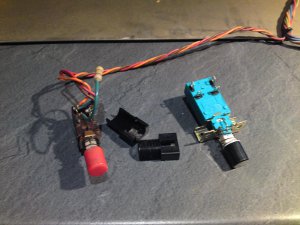
It will be connected with double-isolated wiring, the original and actually very dead neon lamp will be replaced by a yellow LED,
glued into the neon lamp holder with some RTV.


Hook it up!

No one would use screw terminals to connect audio signals in these days. Therefore the RV-10 got some new jacks.
Both the 1/4″ and the XLR jacks are completely differential and ground-free thanks to the transformers at the input and output.

Ursa Major Space Station SST-282

Once upon a time, a Space Station from the constellation Ursa Major landed right on my table, making awful noise when set to reverb.

The cause was easily found – one of the op amps in U12, a quadruple legend named 4741. Looking around I found some more of these noise generators in disguise, some of which also not working properly. I decided to use OnSemi MC33079 because of good experiences in other circuits. Needless to say that the engineers who wrote the SST-282’s service manual were proved right:

So I had to calculate the right compensation to eliminate the 2MHz oscillation of the op amps in the filter ciruits. The result was an unaltered frequency respone up to 9kHz, the maximum to expect in a time-discrete system sampling with 16kHz.

The RAMs were another area to work on. I found one of the original MK4015 chips to be defective, but unfortunately no single 4015 or 4027 – not to be confused with the CMOS logic CD4015 and CD4027! – was on stock. At first sight, a 4116 should be a perfect replacement, the additional address line of the 16k chip is on the location of the 4015’s chip enable, which is connected to ground in the Space Station. But this would have been too easy – the 4k chips Ursa Major used have one little difference: their data out pin remains latched for at least 10µs after the CAS line has gone high:

Within this period of the, the data is transferred to the D/A converter for output. Finally I’ve found and tested a solution that allows to replace any number of MK4015 / MK4027 in this and probably other circuits with 4116 or even 4164 RAMs. The exact circuit will vary from application to application, but I’m quite confident that no one will have to worry about replacing 4k DRAMs in the future.  Feel free to contact me for a custom solution – or to have the DRAMs replaced in your SST-282…