ProPSU – a PSU Upgrade for the Prophet 5

The SCI Prohet 5 Synthesizer has thermal issues in the power supply. SCI’s attempt to make do with a single CT secondary winding results in a voltage of up to 25VDC before the 7805 series regulator. The lack of a decent heatsink makes this even worse. Several techs have been rebuilding the stock PSU with either an additional tranformer or by replacing the transformer with a new one with an additional winding, supplying around 9 volts to an additional rectifier.

This modification also requires some work on the reset circuitry, otherwise the RAM contents might be damaged on shutdown. Other typical work covers replacing the thermal interface material, the big filter capacitors and the tantalum capacitors on the PSU board.

I decided to somewhat standardize the PSU maintenance of Prophet 5’s by designing a drop-in replacement PSU board I called the ProPSU. In order not have to temper with the name plate I made a aluminium heat spreader that is tightened to the back (use of some thermal compound is highly advised!) by re-using three of the original screws. The ProPSU board itself will be, after the cable harness is soldered to the ProPSU, bolted to the readily attached heat spreader by means of 3 or 5 M3x16 machine screws.

The ProPSU can be used for both Rev.2 and Rev.3 Prophet 5’s, with either the +12/-5 volts rails for the 2708 EPROMs provided or missing. Both 15V supplies can be adjusted by means of multi-turn presets. An on-board reset circuit switches the “+20V” rail to the mainboard’s reset generator, simulating a quickly discharging filter cap when the +5V supply drops below 4.75 volts. On turn on, the delay of the reset circuit ensures that all voltages are stable.

propsu_top

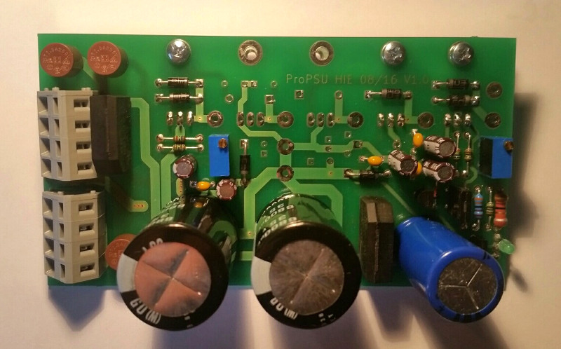
Ready to use ProPSU for late Rev.3 or modified Prophet 5 (new EPROMs, no +12/-5V required)

propsu_mount

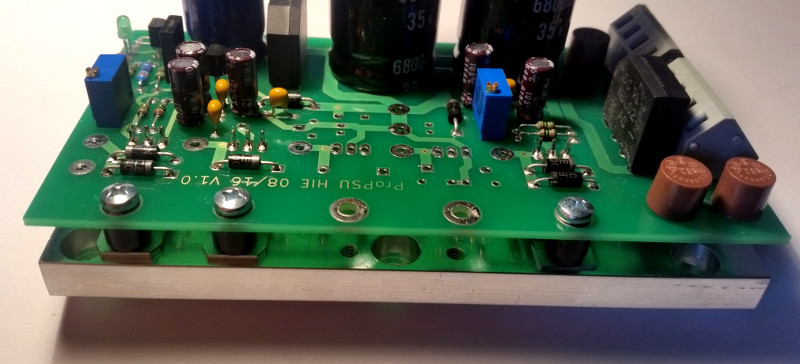
Mounting detail: the heat spreader bar is attached to the bolts of the old PSU’s regulators, after that the ProPSU
PCB is mounted to the heat spreader (isolation washers not shown here)

SCI Pro One – another approach to MIDI

Back in 2007 I developed a replacement PCB for the Pro One’s CPU, not knowing of parallel work on the other side of the ocean.
I planned it to be mounted below the main PCB, just where the old CPU was, but on the other side, but accidently made the PCB too big so that I had to use flat cable to install it.

Some five years later I got another Pro One in need for a new CPU but also for MIDI, so I re-designed the PCB, still with a DIP CPU so that it still needs to be mounted below the mainboard, but now with the correct dimensions.
Keeping in mind that there a much smaller plug-in replacements on the market, I left it this way to allow for DIY building of those daring to solder SMD resistors, but not fine pitch processors.

Here’s the result:

Except from emulating all of the original Pro One’s functions, it can…

Normal and Retrig Mode:

  • use keyboard and MIDI IN in parallel
  • send every key press via MIDI OUT (also in Normal mode, where only lower notes will sound due to low note priority)

Arpeggiator Mode (which has priority over Sequencer Mode in this version, by the way):

  • use keyboard and MIDI IN in parallel during normal and latch mode
  • send the note on/off’s via MIDI OUT as they are played by the arpeggiator, including additionaly hold notes in latched mode

Sequencer Mode:

  • use keyboard or MIDI IN for sequence entry while recording, transpose with keyboard or MIDI IN while playing
  • sends notes via MIDI OUT when local keys are pressed while recording and the notes as they are played while playing
  • offers two independent 100 note memories
  • sequencer memory is non-volatile (saved once leaving the record mode)

The MIDI channel is set by holding down one of the first 16 keys while turning the Pro One on. Every other key will set omni mode.

For the MIDI note assignment I relied on the user’s manual of the Pro One showing the keyboard scale from C0 to C3.
Therefore, the lowest C corresponds to midi #24.

While working on a Rev.1 Pro One one should always keep in mind that the PCB-mounted mains tranformer is much too heavy for the PCB and that the track clearance on the primary side is much too low to comply with any safety standard or electrical code. In this particular case, the transformer was already damaged and had to be replace anyway. This photo shows a possible solution: screw terminal for power cord, protective earth securely bolted to case, fuse in series with mains, double-pole switch with double isolation, toroid tranformer bolted to chassis. The original power connector to the main board has been rewired and re-used.