PPG 390 Drum Unit

One of the most rare PPG units found its way to my workshop recently: the 390 Drum Unit.
PPG 390 Drum Unit

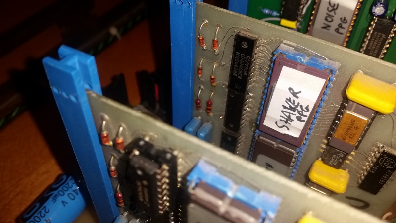
Basically, this is a very rudimentary 8 bit sample player. It features 8 drum sounds in EPROMs on 4 voice cards. Two clock sources drive the address counters on the boards, which means that Sample Freq 1 defines the sampling rate of the odd channels, while Sample Freq 2 is in duty for the even numbered instruments.
[Block diagram to follow…]

Upon arrival one card was missing, instead I found a non working wire-wrapped vero board with a prototype for a single 4kByte instrument in two 2716s, and two 2732 EPROMs with instruments samples that won’t fit anywhere. I designed a PCB to replace the missing voice card, providing sockets for 2764 EPROMs so experimenting with other samples woule be easier as they can be programmes with cheap USB programmers.

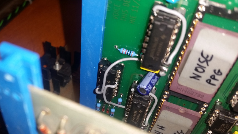
PPG 390 Voice Card

Once completed the design I realized that I cloned the original cards so perfectly that I still don’t have a use for the 2732s – but my layout provides an easy solution, with two piggy-packed 4040 counters and some wires I modified my new voice card to work with the Noise and Hi-Hat EPROMs. Some more wires would allow to experiment with 2764 or even bigger EPROMs.

The clock frequencies are in the range of 13 to 30kHz, so the sound duration is between 70 and 160ms for the originally used 2716 EPROMs and 140 to 320ms for the 2732 sounds and would scale accordingly when using a larger EPROM.

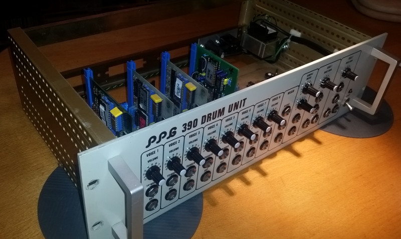
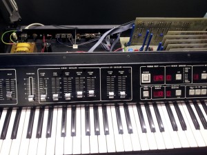
PPG 390 Overview

Apart from this addition, the cards got guides (the blue things) to protect the connectors, new capacitors, additional capacitors in the output lines (originally it had a 3V DC offset), a new transformer, IEC mains jack, a mains fuse and a mains wiring according to current standards.

It is probably not an impressive drum unit sound-wise, but an interesting collectors item and I somewhat like the shaker … 😉

Posted in PPG

PPG 1020: Digital keyboard?

The PPG 1020 is known as the stable successor of the 1002 synthesizer. This was achieved by use of a special oscillator architecture that combines digital octave division and a closed-loop approach including a VCO. The VCO covers the whole range(4 keyboard octaves + approx one more for the “digital modulation” feature), but being within a closed loop, it is stabilized to some degree. The details will be topic of a later blog post. For now we only need to know that we need a digital word that determines the octave and a control voltage to drive the VCO to one out of 12 semitones.

Even without the use of a processor (the 1020 does not have a computer of any kind) it would be straight forward: scan the 49 keys, somehow divide the number of the pressed key modulo 12, the result will be the (already digital) octave number, the remainder drives a DAC to generate the CV.

This “somehow” was actually done by using synchronously counting registers – a chain of 2 binary counters, one turning over at 12, the other incrementing whenever the first one turns over, and a chain of shift registers scanning the keys. The first “high” (pressed key) in the serial pulse train from the shift registers will latch the counter outputs in the next cycle, so we have a low-note priority here.

The counters mentioned above drive the octave control word and a digital-to-analog converter built from two 4051 multiplexers and a chain of accordingly weighted resistors. The reference voltage to that chain is generated on the main board and derived from the setting of the tune knob and the pitch bend slider.

For modulation purposes, an offset is digitally imposed. Since the modulation source from the main board is an analog control voltage, analog-to-digital conversion is necessary. A discrete A/D converter was built from a constant current source generating a linear voltage ramp on a capacitor. This slope is than compared with the modulation voltage in order to reset the above mentioned counters, thereby shifting the generated octave control word and the control voltage. With this approach it is possible to modulate the pitch across an octave border, whereas the analog part of the oscillator control would be limited to variation within an octave.

The comparator in this A/D converter is built from discrete transistors, yet integrated into a CA3086. The same circuit, but under processor control, can be found on the analog panel board (ANIN) of the Wave Computer 360!

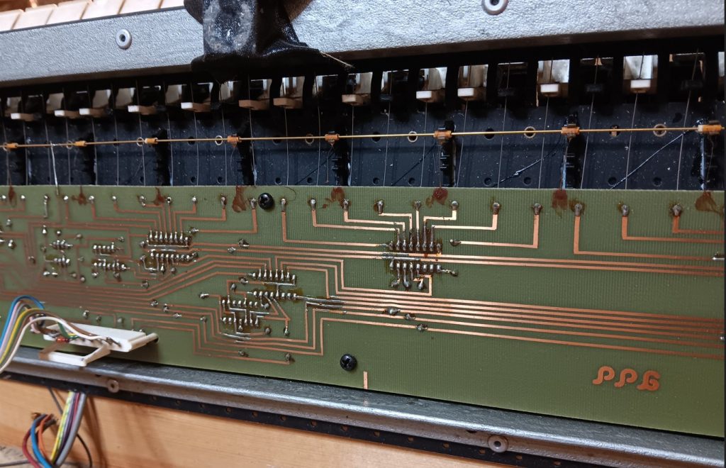
Here’s the component side of the keyboard PCB:
PPG 1020 keyboard PCB components side

While the copper areas in the right top and middle right are of no electrical use, the long copper stripe on the lower edge is actively driven by a delayed clock signal. One might wonder what the reason for this could be – a view on the solder side and some circuit analysis reveals the secret:
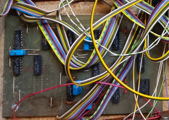
PPG 1020 keyboard PCB solder side

Every key has a 2x1cm big copper area connected to the J-wire on the opposite side. Electrically, each key is capacitively coupled to a delayed clock signal – a signal that is logical “0” whenever the shift registers sample the key lines. This loose coupling is easily overriden by a J-wire touching the bus bar, which is connected to the positive supply voltage by a resistor of just 1k.

The last question about this is: was this only done to eliminate the need for 49 pull down resistors (the shift registers are CMOS devices and would not work properly with open inputs), or were other aspects like debouncing in mind?

A 3.3meg resistor added between one key line and ground suggests that the capacitive pull-down idea did not work 100%.
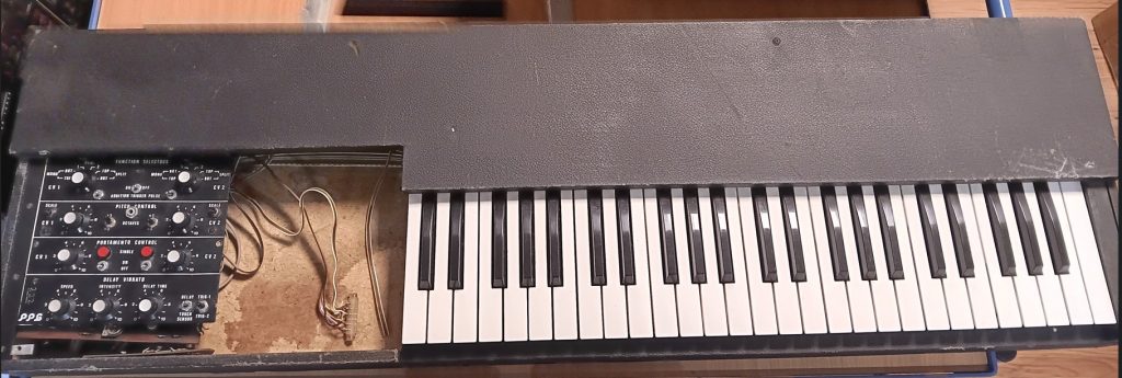
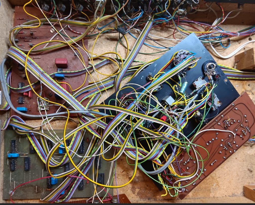
 

Wave Thinking

Today I analyzed a PROZ84 board from a 2.3 with some “odd” sounds.
There was audible distortion, varying with the pitch and the partial wave number.

The oscilloscope revealed (sorry, no image here) that in cases of highest distortion levels only every other sample appeared on the DAC outputs, while the others were at ~0 volts. Half of the partial wave samples having a value of zero is hardly a problem of the wavetable playback, but most likely to be caused by wrong data in the wave RAM.

It turned out that one of the 74S257’s multiplexers outputs in the write circuit had a stuck low output on RAM address line A0, so only even samples were actually written into RAM, with the odd locations containing what is left in the DRAM’s capacitors – in this case, 0.


Update for the Wave 2 modern display firmware

Lately LCD modules showed up that do not comply with the unwritten standard that returning the cursor to home position on a non-shifted display will not take longer than 40 microseconds. The datasheet of the HD44780 controller chip clearly says 40µs up to 1.64ms, with the latter being common for un-shifting shifted displays. A display taking longer than approx 53µs for executing the home command, erratic behaviour will occur.

As the controller originally used in the Wave 2 does not know about shifting, the problem was solved by using a command to explicitely set the cursor position to 0 (zero) instead of the home command.

Here’s the result:


Another 360A leaves the lab

The next PPG 360A has just left the workshop. It seems that all 360A that have been sitting around for years or maybe decades will need several hours of troubleshooting and repair and a bunch of 15..20 ICs.
Fortunately most of the parts are easily available, and the next one is already in work.

As you can see, two boards are missing – between IO and TONRAM there is one of my RAMPROM replacement boards hiding. Less ICs to fail, less power, less heat.

Testing the ELTEC

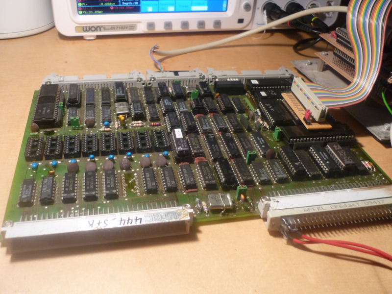
The PPG Waveterm A was built around an industry processor board named EUROCOM II V7 made by ELTEC. Based on a 6809 CPU it contains two 6821 PIAs, a 6850 ACIA with baud rate generator, a 1793 FDC controller, 64k of dynamic RAM and two 4k ROM sockets. One out of three 16k memory pages can be mapped to the integrated discrete monochrom graphics controller.

Due to the complexity it can become rather complicated to trouble shoot those boards. As lots of counters and other TTL ICs are required for the memory to work properly, chances are good that an application’s firmware won’t run due to memory problems.

For the software I’ve created only the CPU, ACIA and baud rate generator need to work. The first routines run completely within the CPU registers and do not require any RAM.
Once started, a welcome message should appear on the connected terminal. If not, basic 6809 system troubleshooting needs to take place.

As soon as the terminal comes to live, the first 4k of RAM will be checked by a AA/55 pattern. If a mismatch occurs, the routine will stop and the original and read bit pattern is displayed.
Assuming the first memory page is in good condition, the stack pointer is initialized and a menu appears.

For now, four tasks are available:
1. Memory test. The whole memory between 1000 and EFFF will be tested, an error will be displayed with the actual address, the written and the read bit patterns. The test will run forever.
2. PIA output. All 8 bit PIA ports show a square wave with a frequency of 19.2kHz on PA0/PB0 decreasing to 150Hz on PA7/PB7.
3. PIA input. Binary patterns of all four 8 bit ports are displayed continuously.
4. Screen test. A test image will be show.

To Do’s:
– add two more test screens, switchable using the page select lines
– add a test for the hardware scrolling functions
– keep away from the FDC, this will have to be troubleshooted in the target system if necessary

ELTEC Eurocom II V7 board under test

A first impression of a Eurocom II on the emulator

White and Blue for the Wave Two

Recent HD44780 based LCDs fit directly to Wave2.3s and can easily be installed into Wave 2.2s. By removing the old HD43160A display controller and adding a 7421, a modern display will work just fine. The 2.2 and 2.3 firmware already have the proper intialization procedures and only need to be convinced to use them by a simple jumper wire.

PPGs Wave 2 was excluded from this upgrade so far because the EPROM code can only deal with the original HD43160A LCD controller. So the old chip has to go at first

HD43160 removed from Wave 2 TAS board

Although the addressing and chip enable signals to the TAS board of the Wave 2 are somewhat different from the TAS82/83 in the 2.2 and 2.3, a valid enable signal for the LCD can easily be generated by addition of a 7421 chip as well.

Wave 2 LCD Wiring

But there’s still the problem with the firmware…

Fortunately, the HD43160A as a predecessor of the HD44780 uses a subset of its command set. Assuming the power-on-reset circuitry of the HD44780 on the new display works well, it would require one additional initialization command to be issued and another command to be modified. The space required for this modification including another delay loop was gained by removing the memory size checks for 6kByte and 32kByte borders, as all Wave 2s known to me have 12kBytes of RAM (excepting the sound RAM). So the memory test has been modified to check whether 12kBytes of usable RAM are available, otherwise throw a ‘9’ to the display to indicate an error.

There are two more locations in the firmware causing trouble: the HD43160A obviously needs the cursor to be re-enabled after some other operations, which is a command 04hex for the 43160. For the 44780 this means to write the characters from right to left, so these commands had to be found and were simply removed for now, as it does not seem necessary for the HD44780 to re-enable the cursor anymore.

Finally it was worth the trouble:

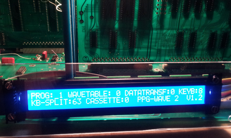
Wave 2 with new display


Old, new, white, blue

Something old – a PPG Wave 2.2 or 2.3,
something new – a 40×2 LCD,
something white – the LED backlight,
something blue – the background color

That’s the recipe for replacing a fading or just boring display in a PPG Wave, and here is how it looks like:

This is a drop-in replacement for all 2.2/2.3 that are already using the new HD44780-compatible display. It can be easily recognized – it is somwhat smaller than the old ones, revealing the metal frame on the front panel, and is mounted on some metal. Old 2.2 with the TAS82 require the on-board controller to be removed and some additional circuitry installed. The firmware is aware of both types.
Even refitting of Wave 2’s will be possible soon, I’m working on a firmware patch to allow the new type to be used with the Wave 2 as well.

And as a special gift, you get rid off that squealing noise of the inverter 🙂

To give you an impression how it would look like in ePaper-style – black on white – I’ve mounted  another display in the Wave. This type requires drilling some new holes, otherwise the LCD appears shifted to the right:

Wave 2 with backlit display…

A How-NOT-to-do-it guide

This Wave 2 owner decided that his PPG also requires a backlit display.
No problem so far. But the datasheet of the EL foil backlight stating that it need 200 to 250 volts AC obviously led to a very wrong decision:

What we see here is an AWG28 2-wire cable ripped off from some flat cable, soldered to the primary lugs of the mains transformer -or, in other words – directly to the 230 VAC mains.
The other end is connected to the EL foil behind the LCD. Even the cheapest alarm clocks from the 70’s running EL illumination from the mains had at least a protective resistor in series.