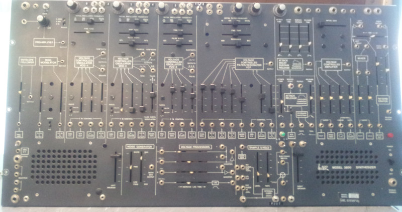
A big one: Arp 2600

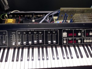
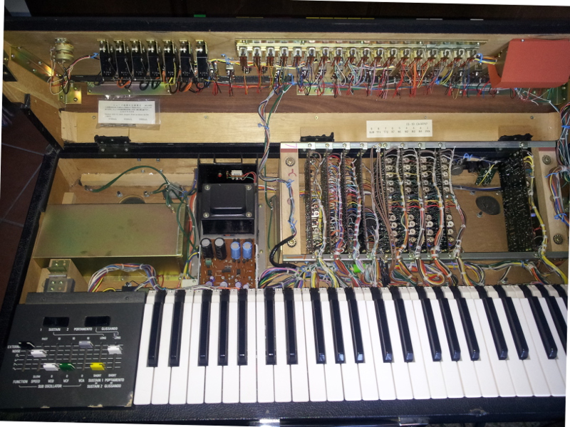
This Arp is here for several reasons. Although a basic repair has already been done before it came in (S&H replaced and some other typical tasks for the 2600), but there is a lot of work to be done. Here’s a first impression of the Arp

There are may modifications, some not yet fully understood. The main problem are several broken potentiometer levers – original parts are not available, nor aren’t rebuilds of similar quality. Therefore we are evaluating levers and knobs made using 3D printing techniques. This work is carried out by drucke3d.de and the parts are now waiting for installation.

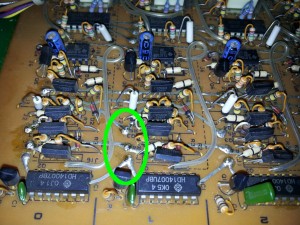
Here are some photos of the major modifications and additions:

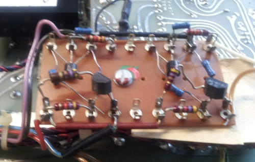
This is a simple 2 transistor astable multivibrator which is actually not connected to any parts of the Arp.
The output signals are routed to separate jacks and may be used for modulation purposes.


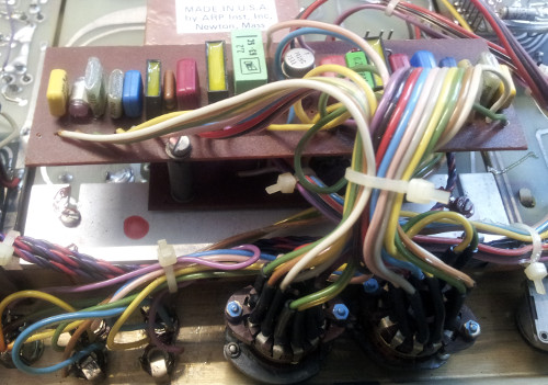
A 2nd order RC filter with switchable corner frequency. The filters are passive with an buffering op amp in between.


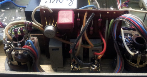
One of the two transpose circuits connected to each of the two VCOs. Two switches expand the transpose possibilites by fourths and fifths.

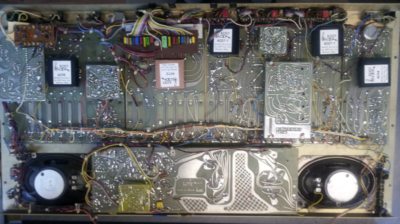
During repair, all modifications will be reverse engineered and documented. For now, here’s an overview of the modules in the Arp:

Another 360A leaves the lab

The next PPG 360A has just left the workshop. It seems that all 360A that have been sitting around for years or maybe decades will need several hours of troubleshooting and repair and a bunch of 15..20 ICs.
Fortunately most of the parts are easily available, and the next one is already in work.

As you can see, two boards are missing – between IO and TONRAM there is one of my RAMPROM replacement boards hiding. Less ICs to fail, less power, less heat.

Korg Trident – Intermittent Problems

After restoring the volume potentiometer from contact cleaner abuse and replacing a bad SSM2044, the Trident still showed some intermittent problems.
One time, the attack on one voice has gone, the next time another voice was lacking release. After some measuring and finally swapping the double transistors, the fault eventually disappeared, but new problems came up.
It turned out that the solder joints of the rivets used as vias on the paper laminate board showed microsopic cracks. Resoldering brought all ADSR features back, needless to say that all rivets of this board need to be reworked.

An example of the affected vias – resolder all of them, there are probably 50+ on this board good for all kind of intermittent trouble.

A side note: this synth uses quite interesting ADSR generators, a 1µF electrolytic is charged and discharged by controlled current sources built around double transistors which are selected by the MOSFETs in a CD4007 package.
The generated envelope controls a VCA built from two selected standard transistors – not always easy to troubleshoot and repair, but the parts are much easier and cheaper to obtain than the typical CEM3310/3360 combo.

AKG ADR68k

An ADR68k showed up with multiple problems and a common symptom: no function, except from the remote telling it cannot find the main unit. The first obvious fault were broken ZIF sockets and an EPROM travelling the 19″ case. Replacing the sockets did not help much, as the power supply was starting to develop a high current smell.
The crowbar circuit tried to force down the linear +5V regulator which is good for up to 10 amps, causing the SCR to get very hot until it finally shorted out. The regulator uses a sense circuit with the power and regulator ground being seperately connected to the main board via a connector – this one:

I know those connectors in a similar or worse condition quite well from pinball games. In this case the resistance of the power return has increased, the regulator tried to compensate and finally lost against the crow bar.

A careful rework of the PSU, including replacement of previously installed cheap capacitors, soldering the wires directly to the main board brought the unit back into operation.

But there still was a input level indication without any signal. It turned out that the PCM53-I DAC in the ADC circuit had an offset on the output and needed to be replaced.


CS50 – CS for CraftsmanShip

After all those plastic synths and heavy metal profile construction with no chance to operate in disassembled state this Yamaha CS50 was a real pleasure to work on. Nice condition and just a minor fault: the external modulation input did not work anymore. There is not much in between the input jack and the modulation source switch – just an OP amp and a capacitor, and unfortunately no protection resistor. This means the OP amp is blown when a high level signal is applied to the modulation input with its level pot turned fully clockwise. After replacing the OP amp and adding a series resistor to protect its input the external modulation was back again.


Evolve!

Some trouble evolved within this Evolver – the barrel jacks permanently failing in laptop computers don’t do better in a synth. Once used on stage, a broken jack, plug, cable… is almost certain. A quick repair on the kitchen table brought it back to live, but a serious improvement would require another connector.

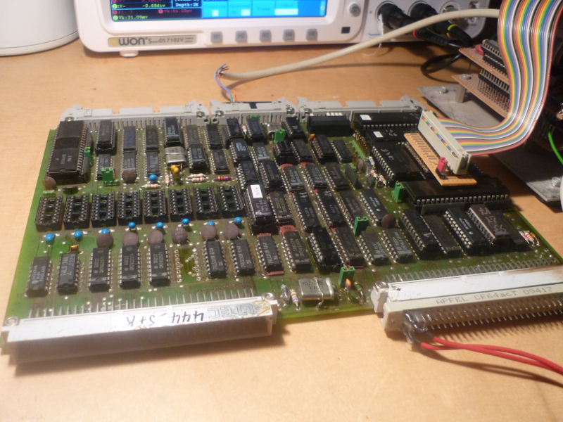
Testing the ELTEC

The PPG Waveterm A was built around an industry processor board named EUROCOM II V7 made by ELTEC. Based on a 6809 CPU it contains two 6821 PIAs, a 6850 ACIA with baud rate generator, a 1793 FDC controller, 64k of dynamic RAM and two 4k ROM sockets. One out of three 16k memory pages can be mapped to the integrated discrete monochrom graphics controller.

Due to the complexity it can become rather complicated to trouble shoot those boards. As lots of counters and other TTL ICs are required for the memory to work properly, chances are good that an application’s firmware won’t run due to memory problems.

For the software I’ve created only the CPU, ACIA and baud rate generator need to work. The first routines run completely within the CPU registers and do not require any RAM.
Once started, a welcome message should appear on the connected terminal. If not, basic 6809 system troubleshooting needs to take place.

As soon as the terminal comes to live, the first 4k of RAM will be checked by a AA/55 pattern. If a mismatch occurs, the routine will stop and the original and read bit pattern is displayed.
Assuming the first memory page is in good condition, the stack pointer is initialized and a menu appears.

For now, four tasks are available:
1. Memory test. The whole memory between 1000 and EFFF will be tested, an error will be displayed with the actual address, the written and the read bit patterns. The test will run forever.
2. PIA output. All 8 bit PIA ports show a square wave with a frequency of 19.2kHz on PA0/PB0 decreasing to 150Hz on PA7/PB7.
3. PIA input. Binary patterns of all four 8 bit ports are displayed continuously.
4. Screen test. A test image will be show.

To Do’s:
– add two more test screens, switchable using the page select lines
– add a test for the hardware scrolling functions
– keep away from the FDC, this will have to be troubleshooted in the target system if necessary

ELTEC Eurocom II V7 board under test

A first impression of a Eurocom II on the emulator

Polysix photocoupler myths

Many Polysix’ will be hit by a sudden photocoupler death somewhen.
There are many “facts” around on the internet describing how do determine whether it has failed and how to substitute the unavailable IC.

Fact 1: it is not true that you can check the photocoupler by measuring the voltage drop on the 4k7 resistor inseries with the LED or even the voltage drop across the LED.
LEDs do fail without exhibiting any dramatic change in electrical parameters. You will find LEDs which drop 1.6 volts @ 20 millamps and emitting no light!
(That – and some scientific applications – is why some applications still require incandescent lamps, and that’s why I’ve designed a controller for a 1960s filament winding machine in 2010!)

In this special case, the LDR saturated at 5.4 megohms with full LED current, so either the LED has become dark or the LDR insensitive.
The only way to check the photocoupler is to remove it from the circuit and measure the LDR resistance versus the LED current and compare it to a known working part (see diagram below)

Some background: the photcoupler is used in a feedback loop to stabilize the expo converter which makes up the V/Hz scale for the VCOs from the octave/V control voltage.
To use only one expo, Korg has used multiplexers to feed the 6 VCO CVs to the expo, followed by a calibration voltage and then the CV for standard pitch (only for the new production voice board).
The two latter outputs are routed to two independent controllers; the last one introduces an offset to the expo input to shift the standard pitch to its desired value, while the converted calibration voltage drives a current through the photocoupler’s LED, while its LDR is placed where you would normally expect the 3300ppm tempco resistor in similar circuits.

This leads to an eady way to check whether a tuning problem is related to the photocoupler circuit at all: measure the voltage on pin 7 of IC18. Within regulation it should be somewhat between -2 and -6 volts, -3 are more normal.
When the loop breaks open due to failure of the photocoupler or related parts, it will be stuck on the maximum negative output, something around -13 volts. There must always be a small current through the LED, otherwise the loop does not work and the TUNE HIGH preset has no effect!

Fact 2: the types VTL5C2 and VTL5C3 which are widely discussed as replacments are simply the wrong choice. In order to make the regulation work, the LDR resistance needs to be in the range of below one to a few kiloohms. The maximum LED current is limited by design to slightly over 2 mA. According to the datasheet, a VTL5C2 has 2 kiloohms at 2mA – regulation will never take place! Even if it seems to work, the controller will work close to the margin and operation cannot be guaranteed. Furthermore, resistance variation is quite large for those devices; the VTL5C2 I have tested had about 20kohms at 1mA.

The diagram below shows a known good original part (blue graph) and a VTL5C9 (yellow graph, values from the datasheet)
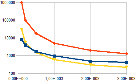
As you may have expected from my previous text, the red line represent the data sheet values for a VTL5C2.
While the VTL5C9 closely matches the original part in the most interesting region, the VTL5C2 resistance is way too high for any current.

What about RoHS…?

Photocouplers with LDRs are, as any LDRs which are commonly based on CdS (cadmium sulphide), forbidden for new products within the EU for some years now.
There is an exemption for the use in electronic music instruments, because there is no practical solution to control varying ac voltages better with LDRs.
(MOSFETs, for example, become highly nonlinear introducing distortion).

In this special case – a closed control loop and very small voltage variation across the device – a photo-mos device would probably be possible.

But it won’t be a solution for the control of audio signals in many applications. The EU has decided that science will have developed and indutry produces an alternative from december 31, 2013 on.
Science hasn’t, and industry doesn’t – except from Macron, who even try to force the EU to withdraw the exemption. Unfortunately, their devices are now way available at major european distributors by now…

Although it is always a good way to reduce hazardous substances, eurocracy has lost any sense of proportion for this topic. While power toys (sorry, I refuse to claim such crap tools) with short life spans flooding the market at low prices are allowed to contain batteries with large amounts of Cd, small photocouplers containg micrograms of Cd typically used in high-priced gear which will last for decades and serviced in case of a problem are to be banned.



Ready to fly!

After almost two years the SE1 mod is finished. Now intense testing can start.

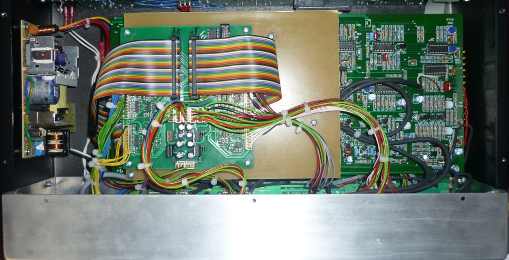
Here’s a quick shot of the new inside. The aluminium back extension contains the six jack boards with all the audio signal amplifiers and CMOS switches. Those boards are connected to the analog PCB of the SE1X directly via shielded cables.
The control board for all the new circuitry resides on top of the SE1X digital and analog boards, shielded with a large copper-cladded FR4 sheet.


The new SE1X has 44 1/4″ jacks – somewhat more than the original two connectors. The meaning of the abbreviated information shown on the labels is explained on the very bottom of this page, so scroll down for a reference until I’ve finished the block diagram.

Cables!

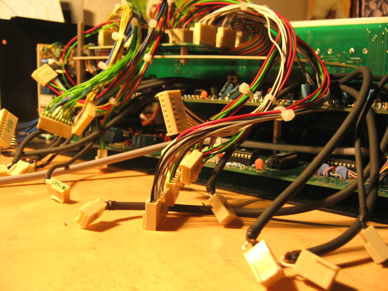
Hopefully the last time I had to remove the back and all the modules for some minor fixes, the SE1X shows all its new wiring here.
The 4o wire ribbon cable has been tapped by the new controller board on top of the original boards. All switching signals and control voltages are handled here.
Shielded cable has been used to interface with the audio signals right on the analog board (which means removing some resistors and cutting some traces – ouch!)

All boards have been tested successfully now with this setup, two potentiometers turned out to be of wrong value for the possible parameter deviation and will be replaced soon.
Goooooooooooo!


But hey, what’s that?

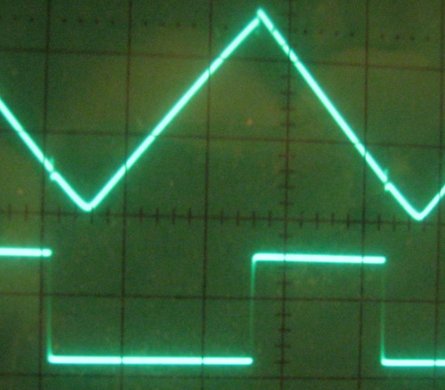
(first of all, for the younger readers: this is a digital photo of an analogue scope screen, with a real cathode ray tube. Yes, I like those things when working with analog signals.)

The lower trace is the output of the RMOD gates (4070 CMOS device) with only VCO2 running, the upper is the triangle wave of VCO2 routed to the output.
First you might think this is a shot-through of the VCA controlling the RMOD amount to the master mix – nope, it is not.
It’s the hard switching of the 4070 causing a spike on the +10 volts rail, making its way into the analogue circuitry.

I’ll have to think about that later.