OB-Xa auto tune demystified

Recently a half repaired OB-Xa hit the workshop. The main trouble was complete failure to auto tune. After fixing some obvious faults (damaged vias, poor quality trimpots) the auto tune issue remained. Although the serial number indicated “old” auto-tune the program LED advanced during auto tune, so the firmware has been upgraded to a revision C already.

Until now I have always ignored that the service manual does say that the Revision C software has a new auto-tune circuit – so I had to learn it the hard way. I measured the gate time of the period meter circuit (which is around 3.82ms for a well tuned VCO, 4 periodes of a high C at 1046,5Hz), measured the clock frequency which is half the crystal clock or 2.4576 MHz. This gives a period count of around 9400.

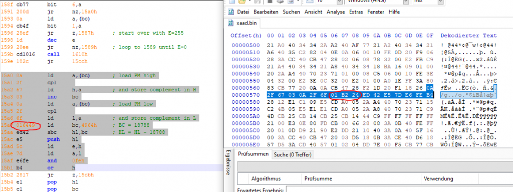
Now I disassembled the firmware and saw that the target count is not in the 9400 range, but twice of that – 18,788 ! I verified my assumptions by feeding a 523Hz clock from a DDS generator which instantly let auto-tune pass.

During this, I also used the great “XACA2” patch EPROM from Ricard Wanderlöf (read here http://butoba.net/homepage/synthhacks.html). We had an email chat for some days trying to evaluate what is happening and came to the conclusion that all out assumptions must be right and that there must be a hardware change as well.

But first my comparison between the XAAD firmware (the last of Revision A) and the XACA disassembly:

While the Revision C compares the period count with 18,788, the old revisions indeed had a target value half as high!

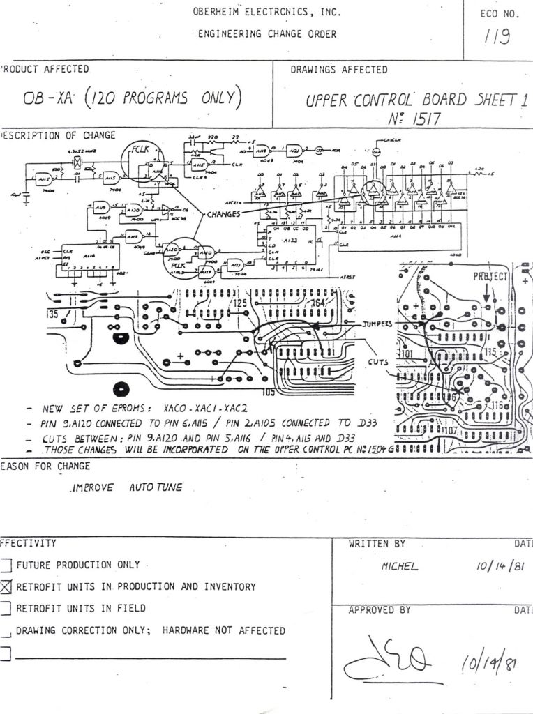
So the only solution to this can be that the period meter is clocked from the full crystal frequency of 4.9152 MHz for Revision C and higher. Half an hour(!) I made this conclusion I found the ECO #119 which explained how to change the upper board for use with the Revision C firmware.

Some times we learn it the hard way. Lots of techs I asked during the process weren’t aware of the hardware modification – or just forgot about it, 40 years later…

Interesting enough: the original schematics of the later mainboard type for the Revision F and G firmware still show the period meter clocked by 2.4576MHz, while the target value in the firmware remains at 18,788. So this must be an error in the diagram, probably not the only one.

Here’s the ECO #119:
Oberheim FVS-1 restoration project

Featured

A nice, but completely not working Oberheim Four Voice came to the workshop some time ago.

First of all, the power supply had to be repaired and converted to 230V mains voltage by using a toroid transformer.
It has been mounted to a small sheet of Al metal to avoid drilling additional holes into the Obie.

After repair and installation of the power supply PCB, the main part of the restoration might begin

(PSU photos to follow)

Every module on the front panel will undergo a thorough treatment: all potentiometers will be removed, opened, cleaned, lubricated and tested. PCBs will be cleaned, checked for cracked solder connections, switched will be cleaned and lubriatced. Electrolytic capacitors will be replaced, and as this model used a special type of film capacitors which tend to crack (sometimes called tropical fish caps due to their color stripes indicating their capacitance value), also the film capacitors will be replaced. Actually several have broken apart from their leads by the slightest touch, so they are no way reliable for continued service. Poor fish.


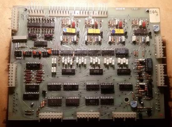
The polyphonic keyboard assigner

This module scans the 61 key keyboard and assigns the generated CV and gate signals to the 4 SEM modules according to the adjustments made on the front panel.

Actually, it should do so, upon arrival, no single gate pulse was seen, nor a correct CV.
A defective 723 caused most of the logic to be without supply. But once energized, a hand full of dead CMOS chips paved the way to a working assigner.

[Photo to follow]

The Programmer

A special module of the four voice is its programmer. It allows to set up various parameters and store them into an internal memory with 16 places, separately for each SEM.
It also features two ADS envelope generators for the SEM’s VCA and for modulating the VCF.

The parameters are:

  • frequency setting (offset to other sources) for both VCOs and the VCF
  • A-D-S for both envelope generators
  • Frequency of an internal LFO, individual to each SEM (called “vibrato”)
  • Amount of LFO to OSCs (1+2 simultaneously)
  • Amount of 2nd envelope to VCF frequency (called “modulation”)

The voltages are converted by a 6 bit A/D converter and then into a bit stream to be either stored into 2 1024 bit SRAMs or bypassed around the memory in manual setting. Due to this, testing and troubleshooting of most parts of the circuits is possible in real time.

Every of the 2 channel boards of the programmer features 4 proprietary envelope generator ICs which are said to be a predecessor of the famous CEM 3310. It is far away from being compatible though, and the custom Oberheim ICs also have an additional VCA integated to the envelope chip.

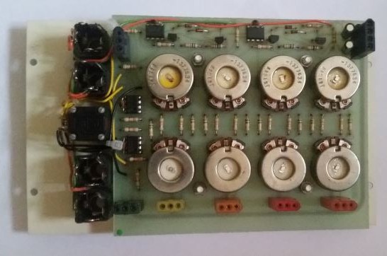
This photo shows the programmer stacked together, with the channel 3&4 board on top. Some CMOS ICs as well as several LM324 had to be replaced here. The cermet presets are kept in place, while the rarely used carbon track presets are to be replaced.

One potentiometer on the programmer’s front panel unfortunately had a severe crack in the resistive track, so I had to mix up parts of the original potentiometer with the track of a brand new 24mm Alpha brand pot.

A set of new T1 3/4 light bulbs completed the programmer.

The output mixer

The Four Voice has an active output mixer with individual volume and pan controls. Apart from cleaning the potentiometers, two of the used µA741 op amps were defective, one had zero output, the other a large offset.
I decided to use NE5534 with approproate compensation here, whereas all other op amps remain original for sound reasons.

The SEM

The hearts – the FVS has four of them – is the famous Oberheim SEM synthesizer module. Once intended for enthusiasts as an add-on to their modulars, it has all relevant connections on Molex connectors on its back side. Several of them are internally routed to other modules, but a modification of this FVS is also in preparation, making it into a modular hybrid.

First of all, the SEMs need to be restored to a working state. Potentiometer cleaning is a bit more complicated because of the special pots used for coarse and fine setting of the VCO frequency.
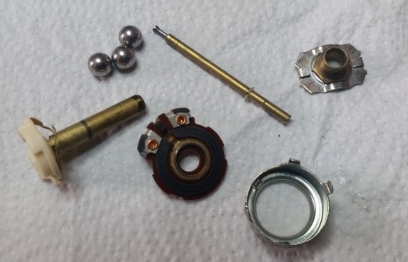
Here’s how this potentiometer looked when disassembled:


After potentiometer and switch maintenance the SEMs will be “re-capped”, tested and repaired where necessary.

I got one working SEM in a break-out case in addition to verify things which was told to sound a lot better than the SEMs of a Two Voice that I have not looked at so far.
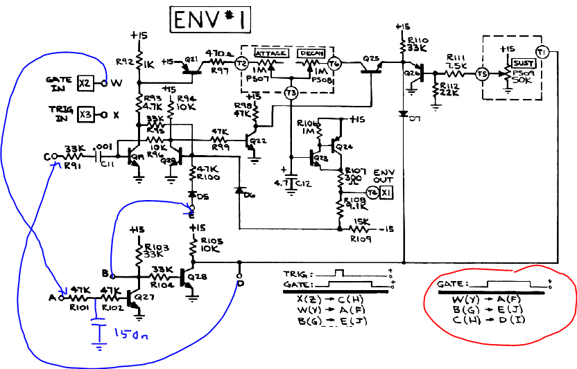
So I compared the SEMs from the FVS with the stand-alone SEM and found that the single SEM was lacking a 150nF capacitor in the gate input circuitry that were present in the FVS SEMs.
I wonder which impact this capacitor might have on sound – it clearly slows down the slope of the gate signal to the trigger circuit and envelope generator.
Will it affect the “snappiness” of a short attack time to an audible extent? Hard to say from the circuit, probably from simulation, but to make things clear I will do some testing once the first SEM is up and running.

Here’s the additional capacitor (no comments on my artwork!)