Variophon: Electrical safety – naaah…

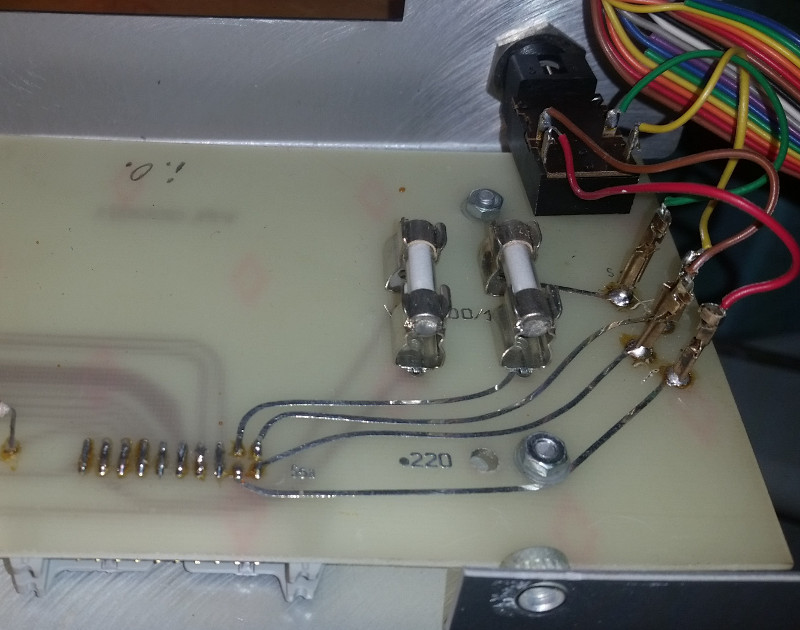
The Realton Variophon, a quite rare electronic wind instrument, is a frightening example how ignorant engineers can be when it comes to safety. While the whole circuit is a very interesting design and far from amateurish, the power supply is a completely no-go. To illustrate what I’m writing about, here’s a photo of the amplifier PCB that carries the mains fuse and switch connections:

  •  mains input is a standard IEC jack with the PE left unconnected, although exposed metal parts are present, but no proper isolation
  • the mains wiring are – 2 AWG28 litz wires from the IEC jack to the board above and 2 AWG 28 wires back to the mains transformer
  • those AWG28 wires are part of a 20 conductor flat cable, entering the PCB in the photo via pins 19 and 20 of the header
  • the track passing the mounting screw, that is actually in direct contact with the metal front plate, is isolated with a small nylon washer
  • the first and only fuse can be seen after the mains switch
  • next to the 4 header pins carrying 230VAC are secondary circuits which are in direct contact with the metal parts of the instrument

The only valid bet would be what happens first – electric shock or fire. This one obviously needs a serious rework.



Beware of the flux

While troubleshooting a Sequential Circuits Prophet 5 synthesizer I came across a quite odd phenomenon: several control voltages, generated by means of multiplexers and some dozens S&H circuits, showed a sawtooth waveform instead of a clean DC voltage. While a falling sawtooth would indicate some ground leakage, I also had some outputs showing a rising sawtooth – so there must be some stray current from a higher potential.

Visual inspection revealed a white, wax-like substance between the pads of some multiplexer IC sockets, obviously flux residue from a previous repair attempt. As both PCB sides were affected, all sockets were removed, the PCB cleaned with isopropyl alcohol. After replacing the parts all control voltage were clean again.


Kicad is not KinderCAD at all

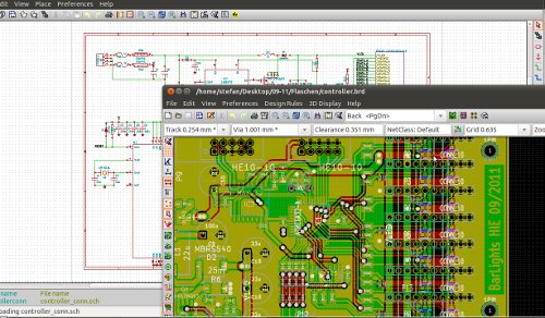
My opinion may be controversial, but I think that the open-source electronics CAD project Kicad from Monsieur Jean-Pierre Charras of the Laboratoire des Images et des Signaux is at least as mature as several high-priced CAD suites.

What do you expect from an all-day schematics and pcb artwork editor? Do you really need high speed design assistants and high frequency modules for every design? I definitely don’t, and therefore I’m quite lucky with Kicad. Sure, the libraries are by far not as complete as for the commercial products. But compared to several products I used in the past Kicad makes it much easier to edit existing or add new components.

I have learned computer-assisted layout design 20 years ago with the DOS-based OrCAD/PCB, tried Eagle in the late 90s, worked with Protel Advanced Schematics / PCB at a former employer and then switched to Protel SE’99 at university. I have never used auto routing so I cannot tell how much better the commerical products are compared to the online routing helper of Kicad, but with regard to easy of use, stability and quality of CAM outputs, Kicad can easily compete.

I have not had any problems with simple post script outputs nor with Gerber file generation yet – something I was not used to, as I often had trouble with mixed unit (imperial/metric) CAM files other programs generated in the past.

Just an example of a little current design

Beware of the fake: CA3080E

Today I was fouled by a parts seller.

The chips pretending to be CA3080E’s made by Intersil will never work as intended because they are fakes.
It’s a sad but common fact that expensive and/or obsolete parts are often counterfeited – either by cloning them (mostly with poor characteristics), re-labelling overstocks or rejects of a completely other chip, or simply selling empty packages. These “3080’s” are of the second kind, there is a die inside and some pn junctions can be measured on the pins. But all of them violate the necessary condition of having a diode junction between pins 5 and 4 (see pg.3 in the data sheet at http://www.intersil.com/data/fn/fn475.pdf ). Another important hint is the date code, which makes these chips rather bad fakes: 15th week 2007 – the competitor National Semiconductor has obsoleted this chip in 1998, so I’d guess that Intersil hasn’t made 3080’s in 2007 anymore.

Update 06-01-2011: The die inside the fake CA3080’s has a name, and its name is LM4250. I’m not sure whether these are good LM4250’s or probably rejects. Either way they won’t substitute for CA3080’s.

Update 07-01-2011: Today I measured a batch of 15 identically looking “3080’s”. I checked for the mentioned diode junction and found it for 2 out of this 15 ICs.
I’ve opened one of them and guess what: there’s a 3080 marking on the die! But as it is mounted in the same cheap-looking package as the LM4250 dies I have serious doubt that these two are real CA3080’s of the expected quality. Here’s an image of the die:

For those who want to read more about counterfeits: http://sound.westhost.com/counterfeit.htm