What we’ve got here is a Lexicon PCM42 delay unit which some techs have already been working on.
While the inital problem was some kind of distortion, the delay path was pretty messed up when it came to me. Well below the yellow LED of the input level indicator was lit the input signal to the A/D converter was heavily clipped.
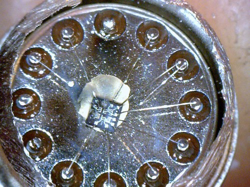
It became clear very soon that the unit uses some kind of compression/expansion technique to virtually increase the A/D and D/A resolution, similiar to A-law or µ-law used in telephony as well as by other music applications realized by simple non-linear amplifiers built around a RCA CA3039 diode array. Some measurements made sure that those diodes were actually not where they’re supposed to be. I did not care whether a defective (how should that be – the array is connected via rather high resistors to the circuit preventing excessive current flow) or fake CA3039 was causing this but ground the thing open:
What we see here is obviously not a fake, but a very dead CA3039. One single diode junction has survived, and judging from the vaporized bond wires, the current must have been rather high – much higher the circuit ever allows.
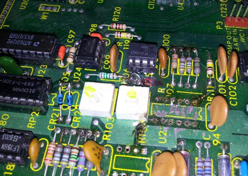
On further examination I found serveral component leads being clipped and soldered back together, maybe to measure those parts out of circuit. Some copper tracks have unfortunately been damaged too.
A rather important 2.55kOhms resistor has not been reconstructed so I decided to restore the unit before doing the actual trouble shooting. After the resistors, capacitors, two diodes, the CA3039 and a LF356 that has previously been identified to be defective had been replaced.
A first test probably showed the initial problem with the PCM: the delayed output was clipping on one half wave at any input level.
Some signal tracing revealed that very first op amp followng the Am6012 DAC in the reconstruction (read: D/A) path showed a 0.6 volts DC offset on the output, way too much to be compensated by the offset trimpot.
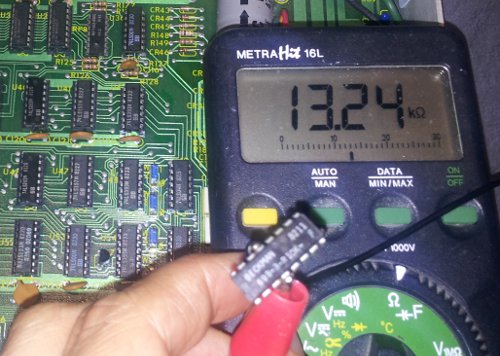
Now there were not many parts left to be checked: the Am6012 DAC chip, the output resistors and the op amp itself. The latter one was easily ruled out by swapping, and as I did not have a AM6012 handy, I checked the resistors. Et voila: each of the two DAC outputs is pulled to an internal +10V reference by two paralleled 10k resistors, being part of a 8x10k DIP array. While 7 of the resistors were well within tolerance, one measured this:
This is more than enough for the measured offset voltage. After replacing the resistor pack by 8 precision resistors the delayed output was clean, symmetrical and free from clipping.
Once again cleaning up after some other’s repair attempts was much more costly than the repair itself. But the most important thing is that a great piece of studio equipment is alive again!


