PPG Waveterm B

Aside from some routine maintenance, this Waveterm B had a little devil sleeping inside for 25+ years now, showing that intuition and being insistent sometimes beat circuit analysis skills.
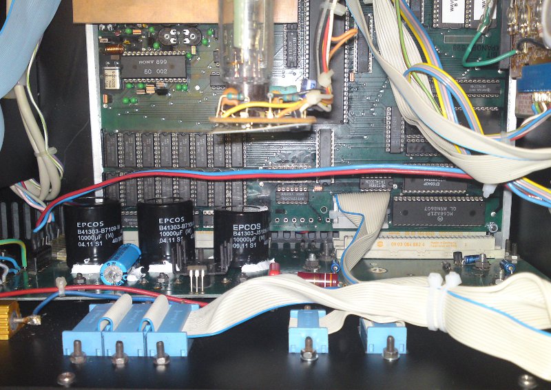
This is the inside of the Waveterm after completion:

What we don’t see:

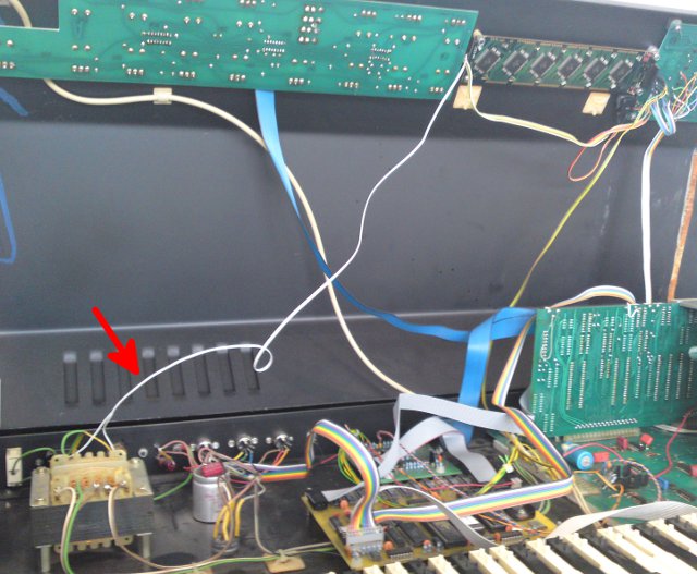
  • complete rewiring of the mains supply to prevent short circuits or even electrocution of poor service personnel
  • new distance bolts and thermal grease for the voltage regulators
  • interconnections between the two computer boards soldered directly to get rid of the flaky connector
  • additional bolts to improve mechanical stability of the PCB sandwhich (see photo below)

What we do see:

  • new electrolytics in the power supply – yes, I dared to re-fit them the PCB, as they are much smaller than the orgininals and won’t get toasted by the DRAMs in full
  • EPROMs had their contents re-written from a known good Waveterm, as one had another checksum as a good dump of the same firmware version
  • All DRAMs at their places

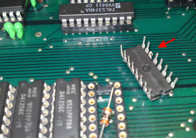
Huh? Where else should they be if not in their sockets?
Hmmm.. let me think… lying in the dust, being stamped on by some heavy state elephants before real pain is being introduced to them?
Something else adequate to compensate for fooling me three hours? No understand?

Look here:

Actually I don’t have much reason to complain. It worked for 25 years this way, much more one would expect from some modern high technology product. And it did work – sometimes, most of the time. But slight knocking would make the 68000 CPU part crash. After bending the DRAMs leg back everything is fine now for the next 25 years.

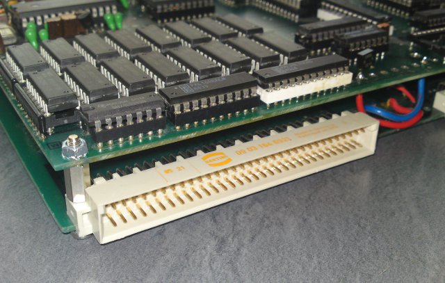
The two computer boards are stacked using some DIP40 sockets below the 6809 CPU and were only secured to each other on one side. To prevent this connection from becoming intermittent, I installed two additional bolts to hold them together on all 4 corners:


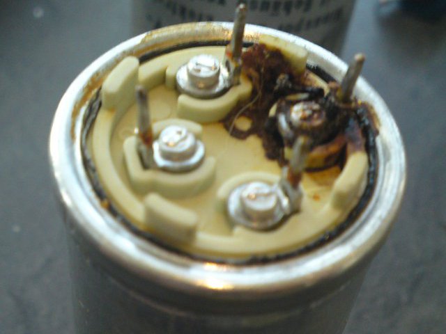
Finally I can show you a good reason to replace an electrolytic capacitor (no, this is not some kind of glue):


Wolfgang Palm : Der Kleine

(The Small / Tiny / Little One)

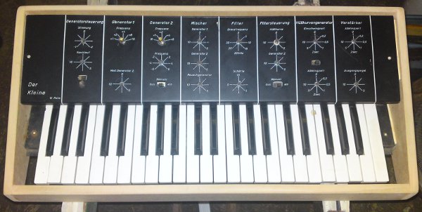
This blog is about the restoration of a very rare synthesizer: Der Kleine made by Wolfgang Palm, only three were built in the early 1970s.

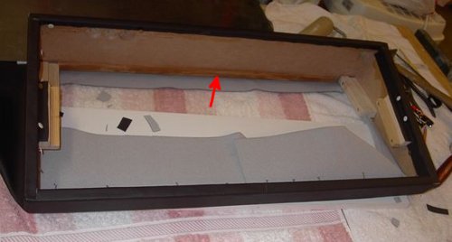
It came to me together with the remainings of something which would eventually have been a case once upon a time. At  the moment, a new housing is being made from medium density fibre board (while chipboard is wood particles with some glue, MDF is just the opposite). Have a look at an early stage here:

In the mean time, the keyboard has been moved up about one centimeter, the spaces left and right from the keyboard are covered and a bottom cover is being cut and drilled these days.
After that, the case will be wrapped in some kind of artificial leather, just like the original.

[Update June 9: Der Kleine getting its new dress]

The red arrow i pointing to the only part taken from the old case for good karma: the wooden strip that supports the operating panel.
All potentiometers and switches will be replaced, a new power supply featuring a toroid transformer and for the first time compliance with the local electrical regulations will be built.
Several capacitors and resistors will be replaced, missing parts added, followed by a first test and calibration. Some more photos of the electronics will follow.

I’ve reverse engineered the circuit, a small service and usage manual will be available for download here soon. I’ll give some details on the circuit as well as on the functions and ranges of the knobs, so it would probably worth to read for musicians as well as for technicians.

The VCO of Der Kleine is somewhat different from the majority of other analog synths: it needs a linear-in-frequency control voltage, the slope will be around -118Hz/V calculated from circuit components.
No, no negative frequency, but negative CV 😉
To allow for external control, I’ll add a trigger input and for compatibility reasons a log-to-lin converter translating the usual V/oct control voltage into the linear scale needed by the oscillator.

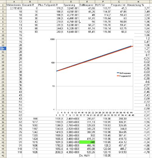
Here’s a screen shot of some calculations done based on the values of resistor string on the keyboard, comparing the frequencies generated by Der Kleine to those of the actual note values (covering the range from F1 to C5)


Wave 2 DRS Adapter

The PPG WAVE2 DRS ADAPTER – demasked

First a short summary of the jacks and switches:
On the left we have 6 phone jacks labelled A to F, one named START/STOP
and a 5pin DIN connector for TAPE SYNC.

Three switches allow to enable a click sound (there’s a small speaker in the DRS box), one to choose between internal or external clock and another to select whether the clock outputs shall be 3 or 4 times the internal timebase.

The phone jacks on the bottom invite the user to feed either a contact-closure or positive voltage trigger signal, the third one labelled INPUT needs to be connected to  the trigger in jack on the Wave 2 – there’s no trigger input pin on the 14pin Amphenol connector, only an output!

Before I start with the description of the 5 right side jacks named CL.1 to CL.5 I’d like to tell all those people who can’t wait to hook this adapter to their Wave 2’s not to have too great expectations, or probably learn some 6809 assembly language.

No, let me start with the bad news instead of the clock outputs. The inputs A-F on the left are not connected within the box. The resistor pack which would close the circuit between the jacks and some port pins of the Wave 2’s VIA chip (which are, for those who really want to hack the firmware, the pins PA4..7 and PB0..1) is not fitted and has never been there.

Furthermore, no known firmware for the Wave 2 – and we know three different versions at the time of writing – has a single line of code that communicates with those port pins in any way.

Now let’s have a look at the circuitry that actually could work.
For understanding it is helpful to know that the Wave 2 has a programmable triple timer chip, a Motorola 6840. Timer #3 generates a clock signal that is normally fed to the clock input of Timer #1 through a 10k resistor. This allows to either tap the internal clock, or to override Timer #3’s output to force an external clock to become the clock source of Timer #1 and thereby control the clock for sequencer, arpeggiator and maybe other functions.

This mixed output/input is connected to the DRS box and directly available on the record out pins of the 5pin DIN jack for tape recorder connection. This allows to record the internal clock to a tape or cassette. In addition the clock signal is routed to two frequency dividers: one, dividing by 8, is selected by the clock switch in the x4 position. By using some advanced mathematics, I was able to calculate that the clock signal generated by Timer #3 is 32 times of … something.
For the x3 position of this switch, Wolfgang and his guys made quite some effort so the x3 clock scaling must have been very important. The clock signal is divided by a binary counter that resets itself when reaching a value of 11, but this would be a little bit too slow to reach 3 times the base clock (32/11 is less than 3, q.e.d.), so the counter is additionally reset whenever the counter of the by-8-divider reaches a value of 32. This way a mean frequency of 3 times something with some jitter is achieved.

Whatever the x3/x4 switch selects is buffered and shows up on the jack CL.1 at 5Vpp. CL.2 to CL.5 carry the clock from CL.1 consecutively divided by 2, 4, 8 and 16. That’s all. It’s up to your imagination what you could do with 3 or 4 times the internal sequencer clock. The CL.4 signal, namely 1/2 or 3/8 of the sequencer clock, makes the speaker click unless told not to do so by the CLICK switch.

If you have recorded some signal to a cassette, you would be able to send it back as the sequencer clock through the DRS box.
The playback pins of the DIN jack are followed by a detector (as simple as a CMOS Schmitt trigger) and a buffer which overrides the clock input of Timer #1 when the switch is set to EXTERNAL.

Finally there’s a START/STOP jack. It’ driven by an inverted version of the CA2 pin of the Wave 2’s VIA chip. When the sequencer is stopped, this pin goes high, disabling all the internal circuity of the DRS box – the counters of the frequency dividers are kept in reset state, and all outputs are forced low, including the tape recording output and the clock jacks.  The START/STOP output is low in this state. It goes high when CA2 becomes low, which is whenever the sequencer is started.

For those who still want to know everything about this little box, here’s the mapping between VIA pins and jacks:

A -> PB0
B -> PB4
C -> PA7
D -> PA4
E -> PA5
F -> PA6

WaveJig: a new helper for PPG Wave 2.2/2.3 voice board repair

Recently two PPG Wave 2.3 voice boards came in crying for help.
As I did not have a 2.3 in the workshop at that moment, I decided to build a test jig that allows to thoroughly check a voice board on the bench – actually much better than in the Wave, because it allows for well defined static levels that can be easily measured.

Here’s a photo for you:

On the left, you see a PPG voice board under test, my jig is plugged right onto it.

What it can do to help trouble shooting by now:
– generate a 20Hz triangle or 1kHz square wave through an arbitrary combination of voices A to D
– apply a control voltage between 0 and 3.5 volts to each VCA, VCF and resonance channel, independent from each other
– choose from any of the four possible time constants (0, 3, 11 and 14ms) for the VCA and VCF control voltages
– modulate the VCA and VCF control voltage for each voice with a 25Hz square wave to ease validation of those time constants

All functions are selected by short commands sent to the board via RS232, eventually by a nice little Tcl/Tk frontend… somewhen…

For now, it already helped me to identify 3 dead CD4066’s and one 74LS379 with a stuck low output – and also revealed a layout mistake on the voice board which prevents the 3 and 14ms time constant for voice D’s VCF from being selected, it will be either 0 or 14ms. Whether the 3 or 14ms setting is ever used is now a task for all 2.3 owners to find out 🙂 Theoretically, it could be audible if the VCF kicks in without a selected 3ms delay.

340A vs Wavecomputer 360A

Someone may ask why one should get a bulky 19″ rack when it is just a re-packaged Wavecomputer 360A.
Of course it is much more than that, although the 340/380 case still contains lots of nothing…

First of all, the 340/380 has the additional 380, the sequencer unit. But the topic of this post are the differences between a Wavecomputer 360A and the 340A/340B combo.
All waves on the Wavecomputer 360A are made up of a fixed set of 64 so called “partial waves” of 128 wave samples each stored in ROM, being unalterable for the user. This is more than enough to have lots of fun, as Kenneth shows us on his website – but for those who even want more fun, the 340 offers flexible partial waves because of its RAM storage. In the original models, the partial waves can (and actually must) be loaded from mini cassette, while this modified model allows for up- and downloading of wave data from and to a PPG Waveterm. At this moment, we can only guess about what would be possible with Armin Stöwe’s Wavecutter Software!

But there’s another thing about the partial waves I can say for sure today. When I wrote that the Wavecomputer 360A had 64 partial waves of 128 samples each, I sugarcoated the machine a bit. As everybody in the 1970s, also Wolfgang had to household with memory space. So he decided to store only half waves of 64 samples each in ROM and calculate the second half by reflecting all wave samples through the origin. This is a simple yet genial thing in digital electronics – he just inverted the wave sample address lines together with the data lines of the wave memory. This is the first step of building the 2’s complement of a binary number, which is the negative representation of the number for most arithmetical operations – and sufficient for the intended task.

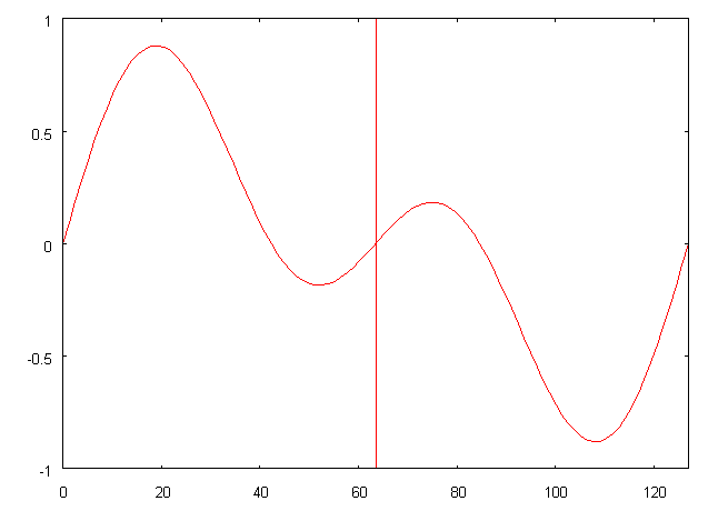
This is a fictional partial wave on the Wavecomputer 360A. The second half (after the vertical red line) is exactly symmetrical to the left half with respect to the origin.
Mathematically said, it fulfills f(x) = -f(-x)  –  the minus before the x is the inversion of the address lines, the minus of the function expression the inversion of the data lines.

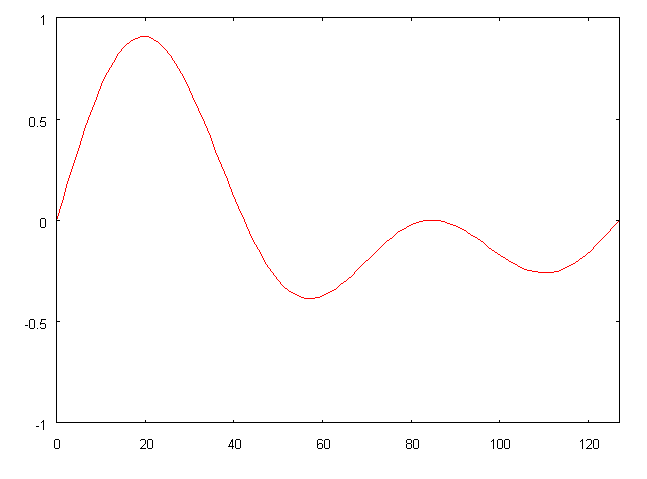
With the PPG 340, this is not necessary anymore.  The TONR module which holds the active partial waves now has 8kBytes of memory, so that the 64 partial waves can be stored completely with 128 wave samples each.
The inverters have been omitted and partial waves like the one below are now possible.

340/380 Common Talk

First, some facts on what this is all about.

PPG’s 340/380 is a wavetable based synthesizer with highly customizable partial waves, 8 voices and a built-in sequencer. It consists of three 19″ boxes, each of them being 3 units high, connected with a 50 wire bus cable.

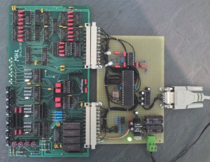
The PPG 340A, called Generator Unit,  contains the Waveomputer 360A’s main board, fitted with four generator boards making up a total of 8 independent voices together with a modified TONR (wave memory) board and the former IO board less the 6802 processor and many other parts.

The PPG 340B is the Processor Unit, containing a new processor board called PER, featuring a 6802 CPU, some RAM, an UART connecting a serial terminal to the 340B, a timer chip, some I/O and circuitry to operate a mini cassette drive. Furthermore, 32kBytes of RAM and 4kBytes of ROM are installed in the 340B. The ROMs originally hold the boot loader allowing to boot the system from mini cassettes.

The third unit is the PPG 380 Event Generator, a highly programmable sequencer. Equipped with the same CPU, ROM and RAM boards as the 340B but with slightly more (48kBytes) RAM it was also booting its actual intelligence from mini cassette. A dual port RAM board interfaces the Event Generator to the mentioned 50 wire bus allowing for high speed messaging from the sequencer unit to the Wavecomputer.

This machine is different from the factory version in so far as Armin Stöwe has promoted it to talk PPG Bus. This way the 340B and 380 are fed with machine code and wave data via the Waveterm, samples can be edited, saved to and loaded from the Waveterm and maybe much, much more… Too sad that we can’t ask Armin about that anymore.