Wave Thinking

Today I analyzed a PROZ84 board from a 2.3 with some “odd” sounds.
There was audible distortion, varying with the pitch and the partial wave number.

The oscilloscope revealed (sorry, no image here) that in cases of highest distortion levels only every other sample appeared on the DAC outputs, while the others were at ~0 volts. Half of the partial wave samples having a value of zero is hardly a problem of the wavetable playback, but most likely to be caused by wrong data in the wave RAM.

It turned out that one of the 74S257’s multiplexers outputs in the write circuit had a stuck low output on RAM address line A0, so only even samples were actually written into RAM, with the odd locations containing what is left in the DRAM’s capacitors – in this case, 0.

 

Old, new, white, blue

Something old – a PPG Wave 2.2 or 2.3,
something new – a 40×2 LCD,
something white – the LED backlight,
something blue – the background color

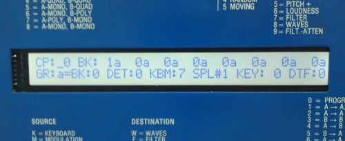
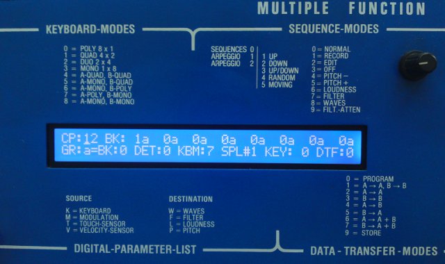
That’s the recipe for replacing a fading or just boring display in a PPG Wave, and here is how it looks like:

This is a drop-in replacement for all 2.2/2.3 that are already using the new HD44780-compatible display. It can be easily recognized – it is somwhat smaller than the old ones, revealing the metal frame on the front panel, and is mounted on some metal. Old 2.2 with the TAS82 require the on-board controller to be removed and some additional circuitry installed. The firmware is aware of both types.
Even refitting of Wave 2’s will be possible soon, I’m working on a firmware patch to allow the new type to be used with the Wave 2 as well.

And as a special gift, you get rid off that squealing noise of the inverter đŸ™‚

To give you an impression how it would look like in ePaper-style – black on white – I’ve mounted  another display in the Wave. This type requires drilling some new holes, otherwise the LCD appears shifted to the right:

WaveJig: a new helper for PPG Wave 2.2/2.3 voice board repair

Recently two PPG Wave 2.3 voice boards came in crying for help.
As I did not have a 2.3 in the workshop at that moment, I decided to build a test jig that allows to thoroughly check a voice board on the bench – actually much better than in the Wave, because it allows for well defined static levels that can be easily measured.

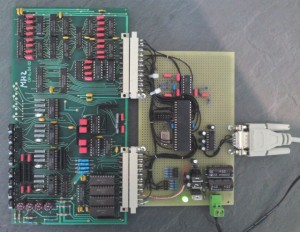
Here’s a photo for you:

On the left, you see a PPG voice board under test, my jig is plugged right onto it.

What it can do to help trouble shooting by now:
– generate a 20Hz triangle or 1kHz square wave through an arbitrary combination of voices A to D
– apply a control voltage between 0 and 3.5 volts to each VCA, VCF and resonance channel, independent from each other
– choose from any of the four possible time constants (0, 3, 11 and 14ms) for the VCA and VCF control voltages
– modulate the VCA and VCF control voltage for each voice with a 25Hz square wave to ease validation of those time constants

All functions are selected by short commands sent to the board via RS232, eventually by a nice little Tcl/Tk frontend… somewhen…

For now, it already helped me to identify 3 dead CD4066’s and one 74LS379 with a stuck low output – and also revealed a layout mistake on the voice board which prevents the 3 and 14ms time constant for voice D’s VCF from being selected, it will be either 0 or 14ms. Whether the 3 or 14ms setting is ever used is now a task for all 2.3 owners to find out đŸ™‚ Theoretically, it could be audible if the VCF kicks in without a selected 3ms delay.