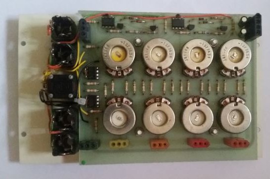
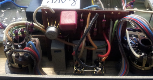
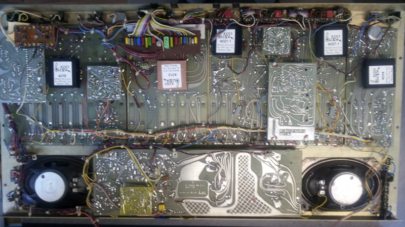
The Four Voice has an active output mixer with individual volume and pan controls. Apart from cleaning the potentiometers, two of the used µA741 op amps were defective, one had zero output, the other a large offset.
I decided to use NE5534 with approproate compensation here, whereas all other op amps remain original for sound reasons.
Author Archives: StefanHuebner
The SEM
The hearts – the FVS has four of them – is the famous Oberheim SEM synthesizer module. Once intended for enthusiasts as an add-on to their modulars, it has all relevant connections on Molex connectors on its back side. Several of them are internally routed to other modules, but a modification of this FVS is also in preparation, making it into a modular hybrid.
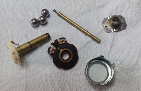
First of all, the SEMs need to be restored to a working state. Potentiometer cleaning is a bit more complicated because of the special pots used for coarse and fine setting of the VCO frequency.
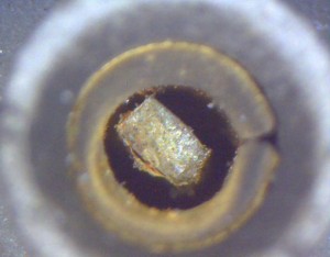
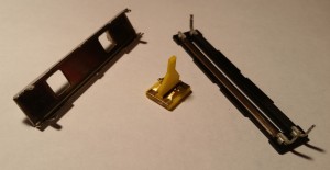
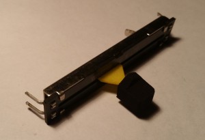
Here’s how this potentiometer looked when disassembled:
After potentiometer and switch maintenance the SEMs will be “re-capped”, tested and repaired where necessary.
I got one working SEM in a break-out case in addition to verify things which was told to sound a lot better than the SEMs of a Two Voice that I have not looked at so far.
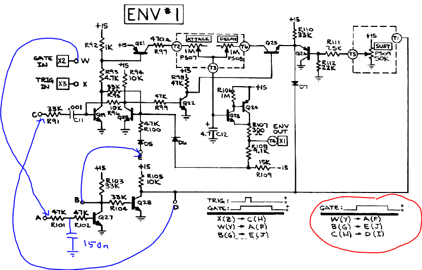
So I compared the SEMs from the FVS with the stand-alone SEM and found that the single SEM was lacking a 150nF capacitor in the gate input circuitry that were present in the FVS SEMs.
I wonder which impact this capacitor might have on sound – it clearly slows down the slope of the gate signal to the trigger circuit and envelope generator.
Will it affect the “snappiness” of a short attack time to an audible extent? Hard to say from the circuit, probably from simulation, but to make things clear I will do some testing once the first SEM is up and running.
Here’s the additional capacitor (no comments on my artwork!)
SCI Pro One – another approach to MIDI
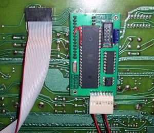
Back in 2007 I developed a replacement PCB for the Pro One’s CPU, not knowing of parallel work on the other side of the ocean.
I planned it to be mounted below the main PCB, just where the old CPU was, but on the other side, but accidently made the PCB too big so that I had to use flat cable to install it.
Some five years later I got another Pro One in need for a new CPU but also for MIDI, so I re-designed the PCB, still with a DIP CPU so that it still needs to be mounted below the mainboard, but now with the correct dimensions.
Keeping in mind that there a much smaller plug-in replacements on the market, I left it this way to allow for DIY building of those daring to solder SMD resistors, but not fine pitch processors.
Here’s the result:
Except from emulating all of the original Pro One’s functions, it can…
Normal and Retrig Mode:
- use keyboard and MIDI IN in parallel
- send every key press via MIDI OUT (also in Normal mode, where only lower notes will sound due to low note priority)
Arpeggiator Mode (which has priority over Sequencer Mode in this version, by the way):
- use keyboard and MIDI IN in parallel during normal and latch mode
- send the note on/off’s via MIDI OUT as they are played by the arpeggiator, including additionaly hold notes in latched mode
Sequencer Mode:
- use keyboard or MIDI IN for sequence entry while recording, transpose with keyboard or MIDI IN while playing
- sends notes via MIDI OUT when local keys are pressed while recording and the notes as they are played while playing
- offers two independent 100 note memories
- sequencer memory is non-volatile (saved once leaving the record mode)
The MIDI channel is set by holding down one of the first 16 keys while turning the Pro One on. Every other key will set omni mode.
For the MIDI note assignment I relied on the user’s manual of the Pro One showing the keyboard scale from C0 to C3.
Therefore, the lowest C corresponds to midi #24.
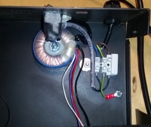
While working on a Rev.1 Pro One one should always keep in mind that the PCB-mounted mains tranformer is much too heavy for the PCB and that the track clearance on the primary side is much too low to comply with any safety standard or electrical code. In this particular case, the transformer was already damaged and had to be replace anyway. This photo shows a possible solution: screw terminal for power cord, protective earth securely bolted to case, fuse in series with mains, double-pole switch with double isolation, toroid tranformer bolted to chassis. The original power connector to the main board has been rewired and re-used.
Restoration of EMT 250s
The model 250 digital reverberator from EMT is quite special. First of all, it looks like the oil radiator from Uhura’s boudoir. In germany the EMT 250 is usually called <Weltraumheizung> (space radiator) because of that.
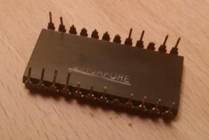
As the developers of the digital circuit, Dynatron, feared that their design could be copied they removed all markings from the ICs – and there are many – of the logic board. Only the RAMs and some static shift registers used for pre-delay are usually untouched.
The main logic board is completely wire-wrapped, something not seen that often outside of vintage industrial control, aircraft and military equipment.
(Images an some info on the first 250 I worked on will follow…)
The second 250 was hit much harder. Some kind of heavy corrosion destroyed about two dozens of ICs. Their pins look rusty and broke off partially while trying to pull the ICs from their sockets. All of them seem to be from one manufacturer, other ICs with a different looking body do not show any traces of corrosion.
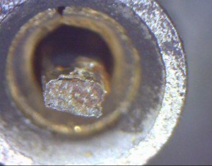
Further investigation with a microscope immediately after removing an IC revealed that some pins were already broken some time before the attempt to pull the IC:
The next task is now to remove the remainings of the pins, clean the sockets and re-populate the board with ICs.
Beware of the flux
While troubleshooting a Sequential Circuits Prophet 5 synthesizer I came across a quite odd phenomenon: several control voltages, generated by means of multiplexers and some dozens S&H circuits, showed a sawtooth waveform instead of a clean DC voltage. While a falling sawtooth would indicate some ground leakage, I also had some outputs showing a rising sawtooth – so there must be some stray current from a higher potential.
Visual inspection revealed a white, wax-like substance between the pads of some multiplexer IC sockets, obviously flux residue from a previous repair attempt. As both PCB sides were affected, all sockets were removed, the PCB cleaned with isopropyl alcohol. After replacing the parts all control voltage were clean again.
Sliding again
As if disassembling and cleaning all linear pots of this ARP 2600 is not enough to deal with, several levers were also broken and missing, together with the caps.
Amadeus from drucke3d.de made a 3D CAD model from the parts of a broken slider pot, evaluated the best production method and had some new levers sintered for me.
The caps could be made on a typical 3D printer.
All parts cleaned, waiting for assembly
Eveything lubricated and put back together
Good sliding action and no dropouts anymore. Mission accomplished 🙂
Wave Thinking
Today I analyzed a PROZ84 board from a 2.3 with some “odd” sounds.
There was audible distortion, varying with the pitch and the partial wave number.
The oscilloscope revealed (sorry, no image here) that in cases of highest distortion levels only every other sample appeared on the DAC outputs, while the others were at ~0 volts. Half of the partial wave samples having a value of zero is hardly a problem of the wavetable playback, but most likely to be caused by wrong data in the wave RAM.
It turned out that one of the 74S257’s multiplexers outputs in the write circuit had a stuck low output on RAM address line A0, so only even samples were actually written into RAM, with the odd locations containing what is left in the DRAM’s capacitors – in this case, 0.
New hope for Morley
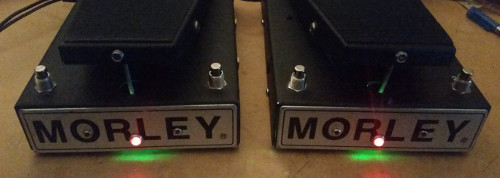
As green is said to be the color of hope, those two oldies should now have lots of it.
They came to me with the classic light bulb, one missing the photo resistor, and both featuring a nice 115VAC transformer and a power cord good for an average home.
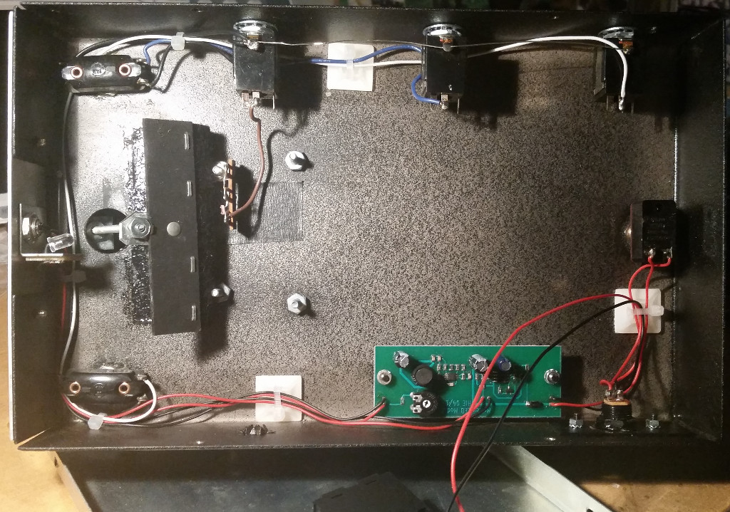
The task was to identify a suitable photo resistor (bad, bad CdS stuff that the EU does not want us to use anymore. Maybe they think all the cadmium is urgently needed for cheap chinese power tools that find an early end in the dustbin due to their quality anyway?), remove the circuitry and design a driver circuit for a LED – a green one, matching with the sensitivity maximum of the photo resistor. A switch mode converter was used to allow the longest possible operation from 9 volts battery. For this purpose, a battery compartment has been mounted into the base plate. As soon as the battery voltage drops below 7.5 volts, the red indicator LED on the front starts flashing slowly.
Here’s the new circuitry:
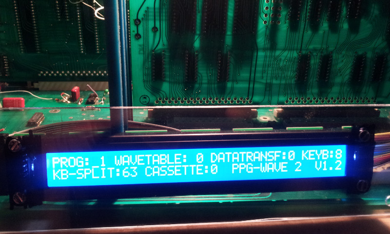
Update for the Wave 2 modern display firmware
Lately LCD modules showed up that do not comply with the unwritten standard that returning the cursor to home position on a non-shifted display will not take longer than 40 microseconds. The datasheet of the HD44780 controller chip clearly says 40µs up to 1.64ms, with the latter being common for un-shifting shifted displays. A display taking longer than approx 53µs for executing the home command, erratic behaviour will occur.
As the controller originally used in the Wave 2 does not know about shifting, the problem was solved by using a command to explicitely set the cursor position to 0 (zero) instead of the home command.
Here’s the result:
A big one: Arp 2600
This Arp is here for several reasons. Although a basic repair has already been done before it came in (S&H replaced and some other typical tasks for the 2600), but there is a lot of work to be done. Here’s a first impression of the Arp
There are may modifications, some not yet fully understood. The main problem are several broken potentiometer levers – original parts are not available, nor aren’t rebuilds of similar quality. Therefore we are evaluating levers and knobs made using 3D printing techniques. This work is carried out by drucke3d.de and the parts are now waiting for installation.
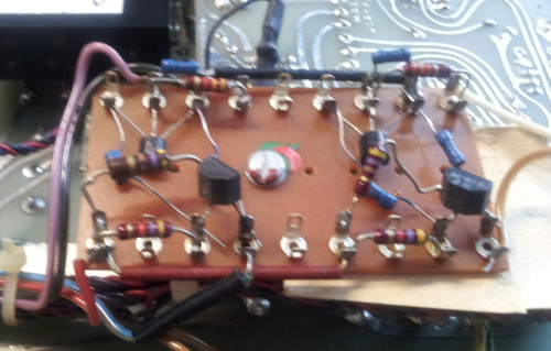
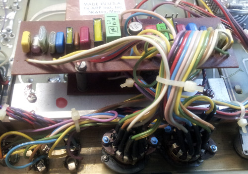
Here are some photos of the major modifications and additions:
This is a simple 2 transistor astable multivibrator which is actually not connected to any parts of the Arp.
The output signals are routed to separate jacks and may be used for modulation purposes.
A 2nd order RC filter with switchable corner frequency. The filters are passive with an buffering op amp in between.
One of the two transpose circuits connected to each of the two VCOs. Two switches expand the transpose possibilites by fourths and fifths.
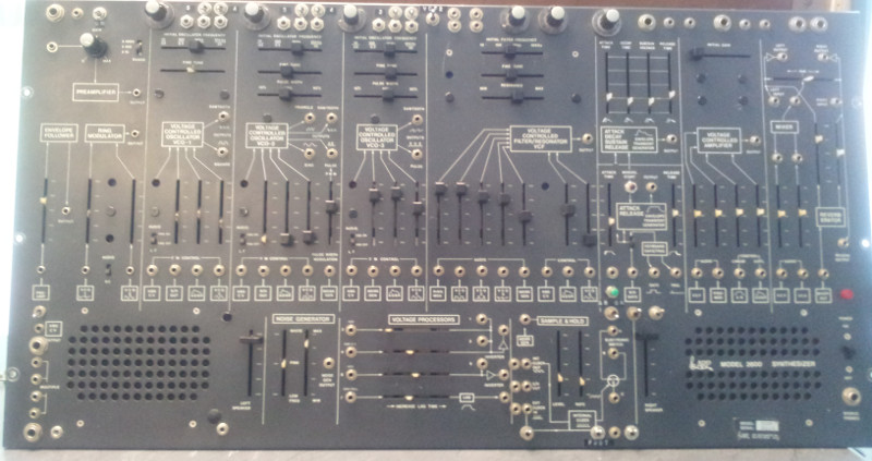
During repair, all modifications will be reverse engineered and documented. For now, here’s an overview of the modules in the Arp:

