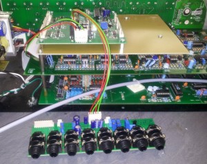
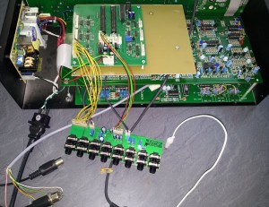
Studio Electronics’ SE1X is a nice 19″ synth module featuring 3 VCOs based on a Moog concept, one Moog-style 24dB ladder filter and a 12dB Oberheim-like switchable lowpass / bandpass filter. The VCOs are capable of sawtooth, triangle and variable-width pulse waveforms; with the addition of a triangle-to-sine converter according to Middlebrook & Richer, the SE1X version generates a sine output instead of triangle on VCO2. Everything is mixed together by classic LM13700 OTAs and finally controlled by two cascaded discrete Moog-style VCAs.
So far everything was strictly analog. The control of all the analog circuits including LFO and envelope generation resides in the digital domain of the central microcontroller. Although the D/A converter used features rather high resolution for internally generated signals, MIDI-only control restricts the actual precision to 7 bits for external control.
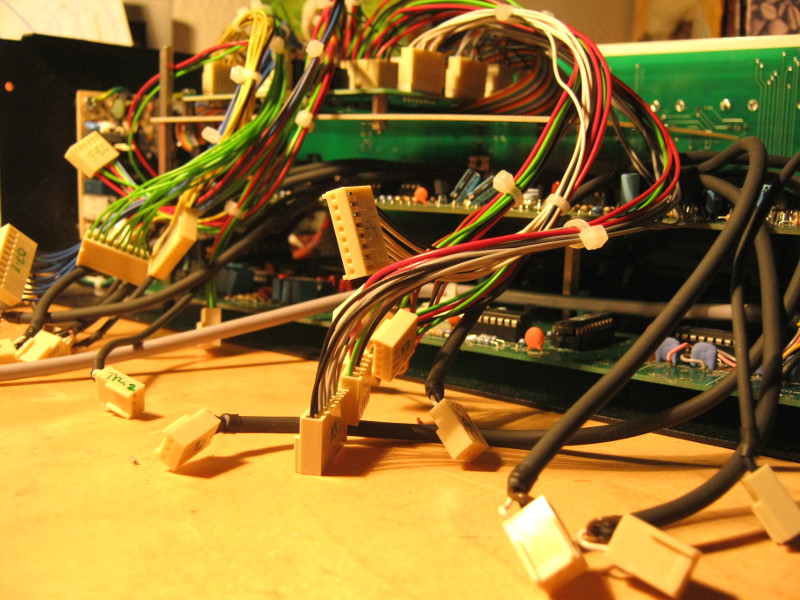
Needless to say that the SE1 needs an option for external CV control, stricly analog. Once we started drilling some holes, why not making the whole thing modular? To cut the story short, after all the component count of the modified SE1 has doubled, a new rear panel was necessary to allow 43(!) jacks to be fitted and 7(!) additional circuit boards to be installed.
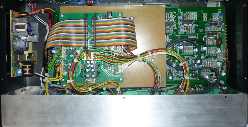
Ready for a peek inside?
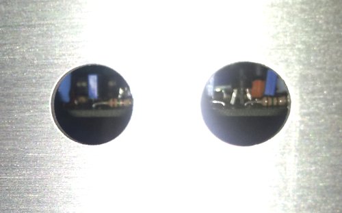
Two out of 43 1/4″ jack holes in the new laser-cut aluminium rear panel grant a peek on the old circuitry
How modular it finally got is probably best described with some photos – stay tuned!
1. The controller board
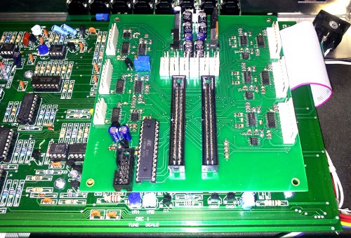
The controller board for the additional circuitry sitting on the SE1 analog board, waiting to be fitted.
By chaining into the 40 conductor flat cable between the SE1 digital and analog boards, the new board has full control over all analog control voltages and digital switch controls signals.
27 OP Amps and 18 CMOS SPDT switch functions take care of proper signal routing. Almost all analog CVs are buffered and routed to output jacks. Each CV has an input jack assigned, followed by protection circuitry and an input buffer. The mechanical contacts in the jacks do not get in touch with the CVs, but control the CMOS switches. Each VCO has an additional CV input which allows to override the internal waveform setting. The same applies for the VCF; a dedicated CV determines whether to use the internal setting or override to one of the three filter types. For ease of A/D conversion of those latter four CVs, the controller board features a small Atmel AVR microcontroller.
2. The VCO jack board (1 out of 3 identical boards)
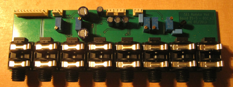
A VCO jack board in a not fully populated state. Most parts reside on the bottom side.
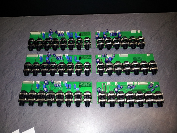
Each VCO gets one of these jack boards with the following features:
VCO CV OUT – a buffered version of the internally generated VCO CV (pitch, frequency, whatever you like)
VCO CV IN – override the internal VCO CV by an external 0..5V control voltage
WAVE SELECT – override the internal VCO waveform setting by an external CV. With this jack board, all three VCOs now offer saw, tri, pulse AND sine and any combination thereof!
WIDTH CV OUT – the internal version of the pulse width control for rectangular wave form. Dim your studio light with it under MIDI control…
WIDTH CV IN – externally control the pulse width of rectangular wave
VCO RAW OUT – the raw output of the VCO, buffered to 0,775Vrms into 10k ohms in triangle mode
MIX IN – disconnects the VCO from the internal mixer and allows an external signal to be inserted (or an effects enriched version of the raw out)
AMOUNT IN – an external 0..5V CV overrides the internal VCO amount setting
There’s no amount out as this control is not modulated or influenced by the envelope generators, but only a representation of the 0-to-63 value set in the SE1’s menu. Too low resolution to be of real use, sorry.
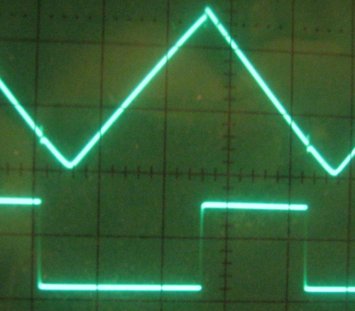
Important: all intermediate outputs (read: all except the main output) are trimmed to 0,775 volts RMS with a triangular signal at 440Hz.
The inputs are adjusted the same, to a patch wire from any intermediate output to its adjacent input will not change the overall signal amplitude.
This allows for transparent insertion of effects, assuming they provide a 0 dB gain.
3. The RMOD/Noise Jack Board
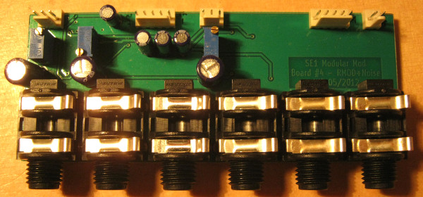
This is the smallest out of the six jack boards of the mod. It provides the following features:
RMOD RAW OUT – the raw output from the ring modulator, trimmed to 0,775 volts RMS with an 440 Hz square wave (50% duty cycle)
RMOD MIX IN – allows to insert an external signal to the RMOD amount VCA, instead of the ring modulator
RMOD AMT IN – override the internal RMOD AMT control by a DC CV of 0..5 volts
NOISE MIX IN – disconnects the noise generator from its amount VCA and replaces it with an external signal (like the external input on a stock SE1X)
NOISE AMT IN – override the internal noise amount control by a DC CV dod 0..5 volts
MIX OUT – a buffered copy of the “master mix”, the sum of the amount VCAs of OSC1..3, RMOD and noise, right before it enters the VCF
4. The VCF jack board
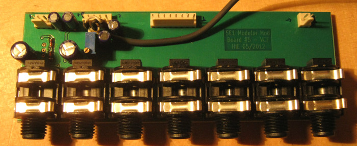
Here’s the board with all the filter controls and signals, look here for its capabilities:
VCF IN – remove the VCF input from the “master mix” and insert an external signal – 0,775V RMS, input impedance 10kOhms, nothing new here…
VCF TYPESEL – a control voltage on this jack selects the VCF operating mode, one out of 12dB LP, 12dB BP or 24dB, overriding the internal setting
CUTOFF OUT – a buffered version of the internal cutoff control voltage (in the range -5..+5 volts!)
CUTOFF IN – overrides the internal cutoff control, same voltage range as for the output of course
RESO OUT – a buffered version of the internal resonance/Q control voltage (0..5 volts)
RESO IN – overrides the internal resonance control
VCF OUT – the buffered and normalized output of the VCF before it enters the VCA
5. Final! The VCA board
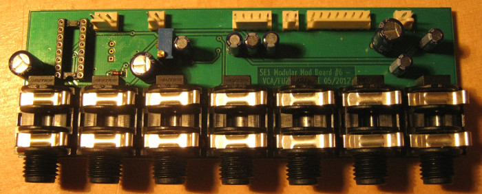
Although two parts are missing, here’s the VCA jack board! Featuring those features:
VCA IN – disconnects the VCA input from the VCF output and allows to insert an external signal. 0,775V RMS, you may have guessed it.
FUZZ AMT – something new: the SE1X’s Fuzzzz has gone variable. Apply a 0..5 volts CV here to control the amount of distortion
VCA1 CV OUT – the internal control voltage for the 1st VCA (controlled by ADSR)
VCA1 CV IN – overrides the internal VCA CV for envelope control
VCA2 CV OUT – the internal control voltage for the 2nd VCA (which is mainly the volume knob’s position)
VCA2 CV IN – overrides the internal volume control
OUTPUT – finally, here’s what you are listening to. The level remained unaltered, which means it is normally somewhat lower than 0.775V RMS.

